X1 +24VDC Logic Supply For
If the control was not ordered with this option, do not connect any voltage to these pins.
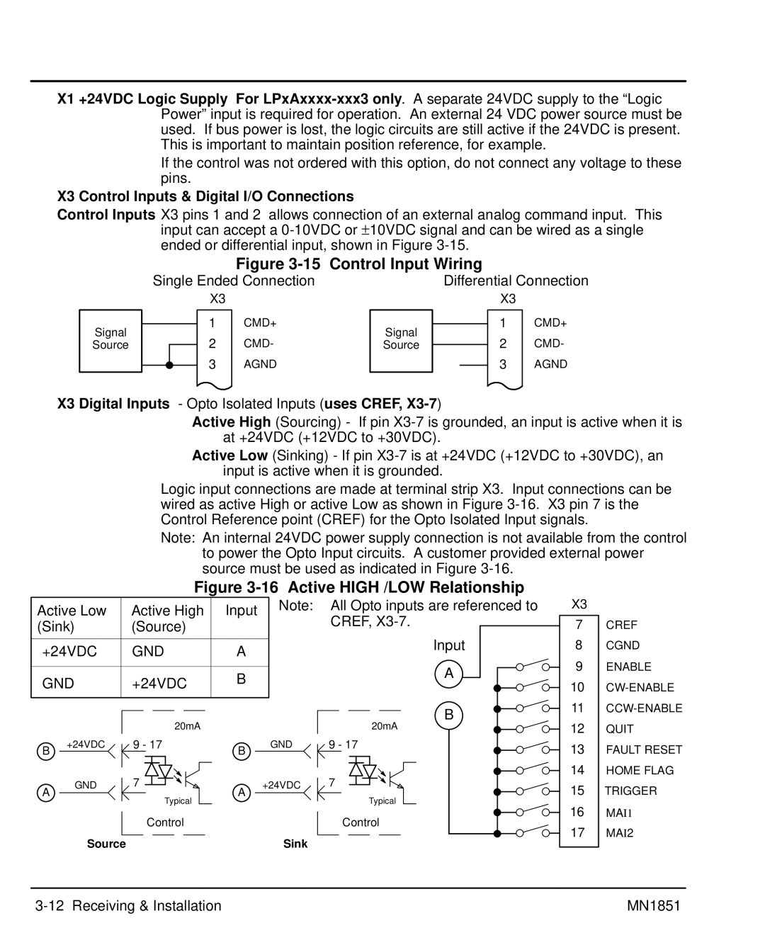
X3 Control Inputs & Digital I/O Connections
Control Inputs X3 pins 1 and 2 allows connection of an external analog command input. This input can accept a
Signal
Source
|
|
| Figure | Control Input Wiring |
| |||
Single Ended Connection |
| Differential Connection | ||||||
|
| X3 |
|
|
|
| X3 |
|
|
|
|
|
|
|
|
|
|
|
| 1 | CMD+ | Signal |
|
| 1 | CMD+ |
|
|
|
| |||||
|
| 2 | CMD- |
|
| 2 | CMD- | |
|
| Source |
|
| ||||
|
|
|
| |||||
|
| 3 | AGND |
|
|
| 3 | AGND |
|
|
|
| |||||
|
|
|
|
|
|
|
|
|
X3 Digital Inputs - Opto Isolated Inputs (uses CREF, X3-7)
Active High (Sourcing) - If pin
Active Low (Sinking) - If pin
Logic input connections are made at terminal strip X3. Input connections can be wired as active High or active Low as shown in Figure
Note: An internal 24VDC power supply connection is not available from the control
to power the Opto Input circuits. A customer provided external power source must be used as indicated in Figure
Figure 3-16 Active HIGH /LOW Relationship
Active Low | Active High | Input | Note: All Opto inputs are referenced to | ||
| CREF, | ||||
(Sink) | (Source) |
|
| ||
|
|
| |||
+24VDC | GND | A |
| Input | |
|
| ||||
GND | +24VDC | B |
| A | |
|
| ||||
|
|
| |||
|
|
|
|
| B |
|
| 20mA |
|
| 20mA |
B | +24VDC | 9 - 17 | B | GND | 9 - 17 |
|
|
|
| ||
A | GND | 7 | A | +24VDC | 7 |
| Typical |
| Typical | ||
|
|
|
| ||
|
| Control |
|
| Control |
| Source |
|
| Sink |
|
X3
7
8
9
10
11
12
13
14
15
16
17
CREF
CGND ENABLE
MAI2
| MN1851 |