PI COMPENSATION
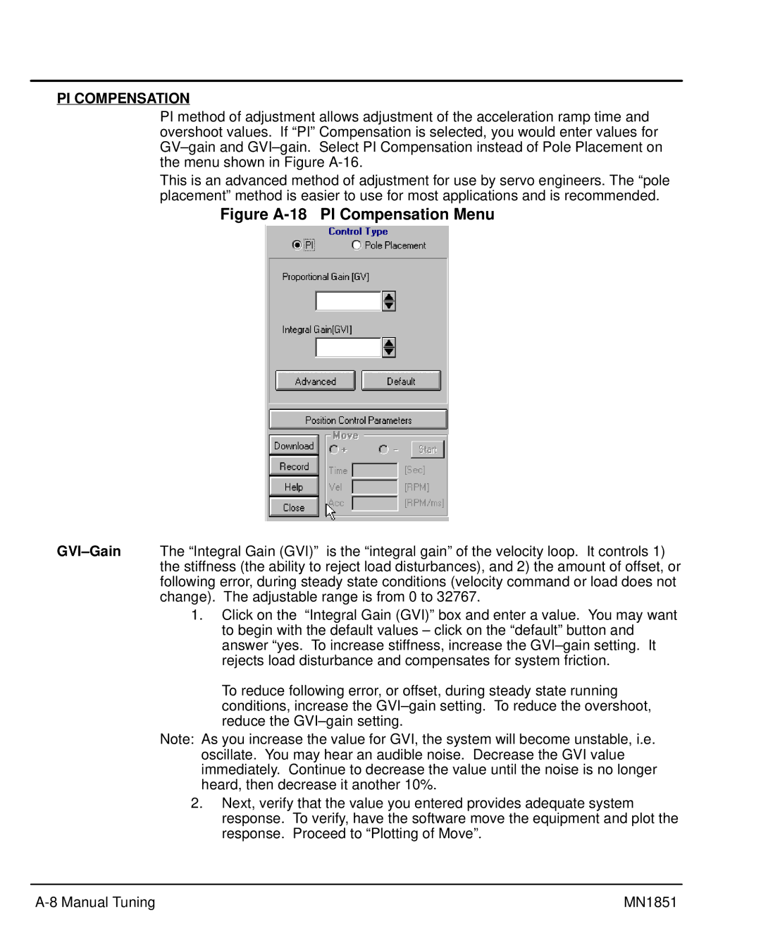
PI method of adjustment allows adjustment of the acceleration ramp time and overshoot values. If “PI” Compensation is selected, you would enter values for
This is an advanced method of adjustment for use by servo engineers. The “pole placement” method is easier to use for most applications and is recommended.
Figure A-18 PI Compensation Menu
1.Click on the “Integral Gain (GVI)” box and enter a value. You may want to begin with the default values – click on the “default” button and answer “yes. To increase stiffness, increase the
To reduce following error, or offset, during steady state running conditions, increase the
Note: As you increase the value for GVI, the system will become unstable, i.e. oscillate. You may hear an audible noise. Decrease the GVI value immediately. Continue to decrease the value until the noise is no longer heard, then decrease it another 10%.
2.Next, verify that the value you entered provides adequate system response. To verify, have the software move the equipment and plot the response. Proceed to “Plotting of Move”.
MN1851 |
