Tables
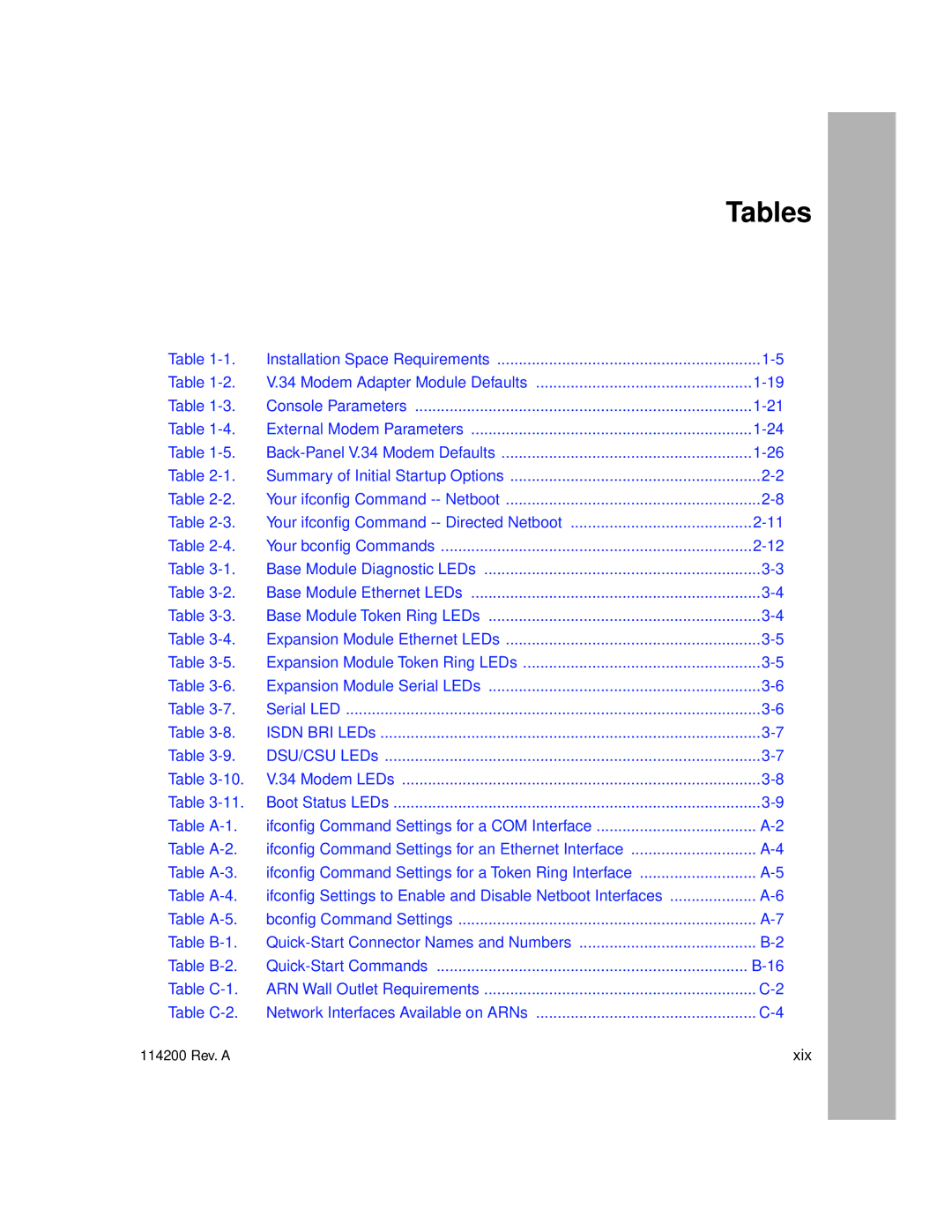
Table | Installation Space Requirements | |
Table | V.34 Modem Adapter Module Defaults | |
Table | Console Parameters | |
Table | External Modem Parameters | |
Table | ||
Table | Summary of Initial Startup Options | |
Table | Your ifconfig Command | |
Table | Your ifconfig Command | |
Table | Your bconfig Commands | |
Table | Base Module Diagnostic LEDs | |
Table | Base Module Ethernet LEDs | |
Table | Base Module Token Ring LEDs | |
Table | Expansion Module Ethernet LEDs | |
Table | Expansion Module Token Ring LEDs | |
Table | Expansion Module Serial LEDs | |
Table | Serial LED | |
Table | ISDN BRI LEDs | |
Table | DSU/CSU LEDs | |
Table | V.34 Modem LEDs | |
Table | Boot Status LEDs | |
Table | ifconfig Command Settings for a COM Interface | |
Table | ifconfig Command Settings for an Ethernet Interface | |
Table | ifconfig Command Settings for a Token Ring Interface | |
Table | ifconfig Settings to Enable and Disable Netboot Interfaces | |
Table | bconfig Command Settings | |
Table | ||
Table | ||
Table | ARN Wall Outlet Requirements | |
Table | Network Interfaces Available on ARNs |
114200 Rev. A | xix |
