Technical Specifications
Note: Refer to the Cable Guide for Routers and BNX Platforms for the proper cables or cable pinouts to use for each interface type.
Ethernet Attachment Unit Interface (AUI)
The ARN Ethernet base module, Ethernet expansion module, and
Note: The AUI is designed only for connection to a transceiver. Connecting the AUI directly to an AUI on an Ethernet station (without a transceiver) violates IEEE 802.3 standards.
Table
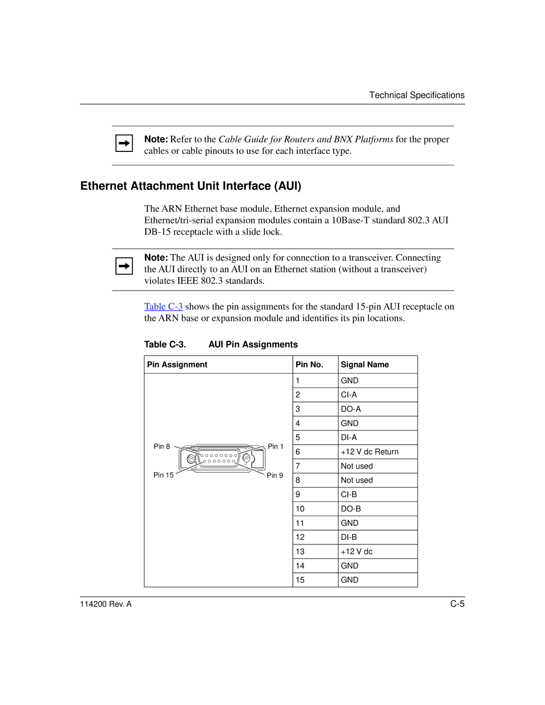
Table | AUI Pin Assignments |
| |
Pin Assignment |
| Pin No. | Signal Name |
|
| 1 | GND |
|
| 2 | |
|
| 3 | |
|
| 4 | GND |
|
| 5 | |
Pin 8 | Pin 1 | 6 | +12 V dc Return |
|
| ||
|
| 7 | Not used |
Pin 15 | Pin 9 | 8 | Not used |
|
| ||
|
| 9 | |
|
| 10 | |
|
| 11 | GND |
|
| 12 | |
|
| 13 | +12 V dc |
|
| 14 | GND |
|
| 15 | GND |
114200 Rev. A |
|
| |