Installing and Operating BayStack ARN Routers
Understanding Quick-Start Connector Names and Numbers
The
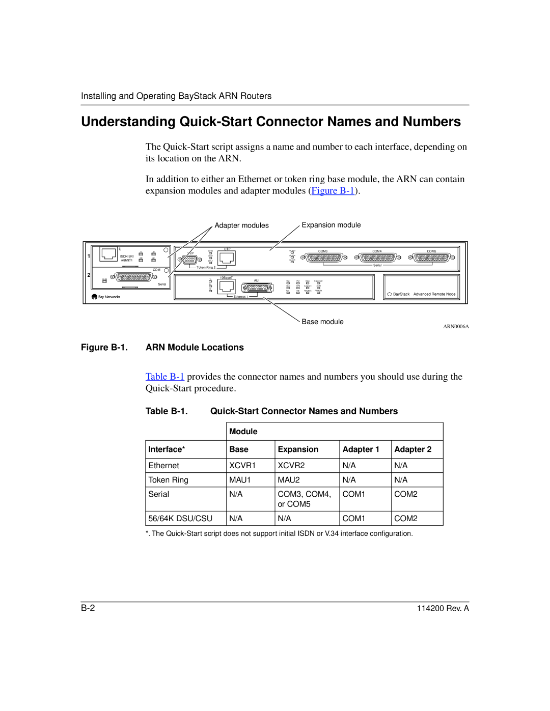
In addition to either an Ethernet or token ring base module, the ARN can contain expansion modules and adapter modules (Figure
Adapter modules | Expansion module |
| U | D | B1 | RCVR | UTP | RLSD3 |
|
| COM3 | COM4 | COM5 |
1 | ISDN BRI |
|
| STP |
| RLSD4 |
|
|
|
|
|
DD |
| NSRT |
|
|
|
|
|
| |||
B2 |
|
|
|
|
|
|
|
| |||
| withNT1 |
|
| WFLT |
| RLSD5 |
|
|
|
|
|
|
|
|
| Token Ring 2 |
|
|
|
|
| Serial |
|
|
|
| COM |
|
|
|
|
|
|
| |
|
|
|
|
|
|
|
|
|
|
| |
2 |
|
|
|
| 10BaseT |
|
|
|
|
|
|
| RLSD |
|
| Tx | AUI | Run | Pwr | Base | Expansion |
|
|
|
|
|
|
|
|
| |||||
|
|
| Serial | Rx |
| Boot | RPS | Adapter1 | DCM |
|
|
|
|
|
| Cl |
| Fail | Fan | Adapter2 | PCMCIA |
|
|
|
|
|
|
|
|
|
| ||||
|
|
|
|
| Ethernet 1 |
|
|
|
| BayStack | Advanced Remote Node |
|
|
|
|
|
|
|
|
|
|
|
Base module
ARN0006A
Figure B-1. ARN Module Locations
Table
Table |
| ||||
|
|
|
|
|
|
|
| Module |
|
|
|
|
|
|
|
|
|
Interface* |
| Base | Expansion | Adapter 1 | Adapter 2 |
|
|
|
|
|
|
Ethernet |
| XCVR1 | XCVR2 | N/A | N/A |
|
|
|
|
|
|
Token Ring |
| MAU1 | MAU2 | N/A | N/A |
|
|
|
|
|
|
Serial |
| N/A | COM3, COM4, | COM1 | COM2 |
|
|
| or COM5 |
|
|
|
|
|
|
| |
56/64K DSU/CSU | N/A | N/A | COM1 | COM2 | |
|
|
|
|
|
|
*. The
114200 Rev. A |