Installing the BayStack Advanced Remote Node
Connecting to a Serial Interface
The ARN supports up to five serial interfaces. You can connect
•Up to three,
•One,
To connect to a serial interface:
1.Locate the
Note: The Cable Guide for Routers and BNX Platforms refers to serial cables that transmit synchronous data as “synchronous” cables.
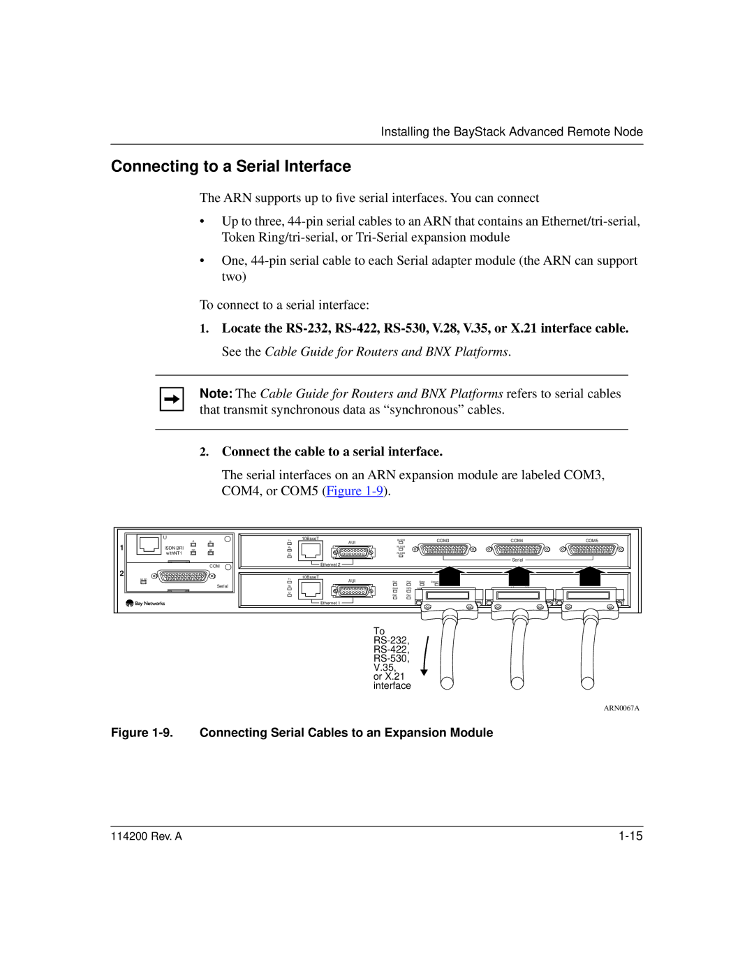
2.Connect the cable to a serial interface.
The serial interfaces on an ARN expansion module are labeled COM3, COM4, or COM5 (Figure
| U | D | B1 | Tx | 10BaseT | RLSD3 |
|
| COM3 | COM4 | COM5 |
1 |
| AUI |
|
|
| ||||||
|
|
|
|
|
|
|
|
|
| ||
ISDN BRI | DD |
| Rx |
| RLSD4 |
|
|
|
|
| |
B2 |
|
|
|
|
|
|
|
| |||
| withNT1 |
|
| Cl |
| RLSD5 |
|
|
|
|
|
|
|
|
|
| Ethernet 2 |
|
|
|
| Serial |
|
|
|
| COM |
|
|
|
|
|
|
| |
|
|
|
|
|
|
|
|
|
|
| |
2 |
|
|
|
| 10BaseT |
|
|
|
|
|
|
| RLSD |
|
| Tx | AUI | Run | Pwr | Base |
|
|
|
|
|
|
|
|
|
|
| ||||
|
|
| Serial | Rx |
| Boot | RPS | Adapter1 | DCM |
|
|
|
|
|
| Cl |
| Fail | Fan | Adapter2 |
|
|
|
|
|
|
|
|
|
|
|
| |||
|
|
|
|
| Ethernet 1 |
|
|
|
| BayStack | Node |
|
|
|
|
|
|
|
|
|
|
|
To
ARN0067A
Figure 1-9. Connecting Serial Cables to an Expansion Module
114200 Rev. A |