Installing and Operating BayStack ARN Routers
LED Descriptions
LEDs on the ARN front and back panels provide information about how the ARN is operating. The following sections describe the LEDs on the ARN base modules, expansion modules, adapter modules, and the ARN back panel.
Base Module LEDs
The ARN base module LEDs include diagnostic LEDs and either Ethernet or token ring interface LEDs.
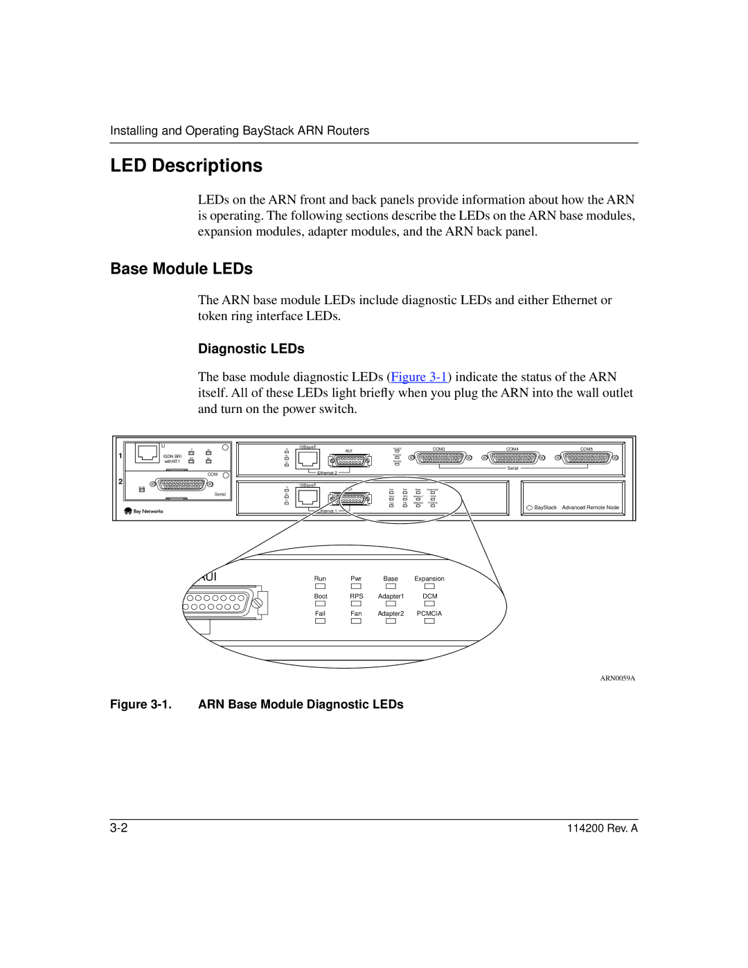
Diagnostic LEDs
The base module diagnostic LEDs (Figure
| U | D | B1 | Tx | 10BaseT | RLSD3 |
|
| COM3 | COM4 | COM5 |
1 |
| AUI |
|
|
| ||||||
|
|
|
|
|
|
|
|
|
| ||
ISDN BRI | DD |
| Rx |
| RLSD4 |
|
|
|
|
| |
B2 |
|
|
|
|
|
|
|
| |||
| withNT1 |
|
| Cl |
| RLSD5 |
|
|
|
|
|
|
|
|
|
| Ethernet 2 |
|
|
|
| Serial |
|
|
|
| COM |
|
|
|
|
|
|
| |
|
|
|
|
|
|
|
|
|
|
| |
2 |
|
|
|
| 10BaseT |
|
|
|
|
|
|
| RLSD |
|
| Tx | AUI | Run | Pwr | Base | Expansion |
|
|
|
|
|
|
|
|
| |||||
|
|
| Serial | Rx |
| Boot | RPS | Adapter1 | DCM |
|
|
|
|
|
| Cl |
| Fail | Fan | Adapter2 | PCMCIA |
|
|
|
|
|
|
|
| BayStack | Advanced Remote Node | ||||
|
|
|
|
| Ethernet 1 |
|
|
|
| ||
|
|
|
|
|
|
|
|
|
|
|
AUI
Run Pwr Base Expansion
|
|
| Boot | RPS | Adapter1 | DCM |
|
|
| Fail | Fan | Adapter2 | PCMCIA |
|
|
|
|
|
|
|
|
|
|
|
|
|
|
|
|
|
|
|
|
|
|
|
|
|
|
|
|
|
|
|
|
|
|
|
ARN0059A
Figure 3-1. ARN Base Module Diagnostic LEDs
114200 Rev. A |