Installing and Operating BayStack ARN Routers
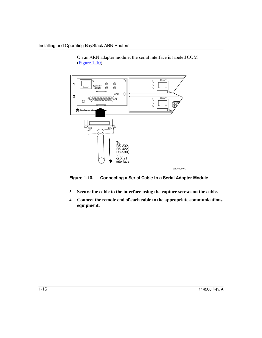
On an ARN adapter module, the serial interface is labeled COM (Figure
| U |
|
| Tx | 10BaseT |
1 | D | B1 |
| ||
|
|
| |||
ISDN BRI |
|
| Rx |
| |
DD |
|
|
| ||
| B2 | Cl |
| ||
| withNT1 |
| |||
|
|
|
| ||
|
|
|
|
| |
|
|
| COM |
| Ethernet 2 |
2 |
|
|
|
| |
|
|
|
| 10BaseT | |
|
|
|
| Tx | |
|
|
|
|
| |
| RLSD |
|
|
|
|
|
|
|
| Rx |
|
|
|
|
| Cl |
|
|
|
|
|
| Ethernet 1 |
To
ARN0066A
Figure 1-10. Connecting a Serial Cable to a Serial Adapter Module
3.Secure the cable to the interface using the capture screws on the cable.
4.Connect the remote end of each cable to the appropriate communications equipment.
114200 Rev. A |