Operating the ARN
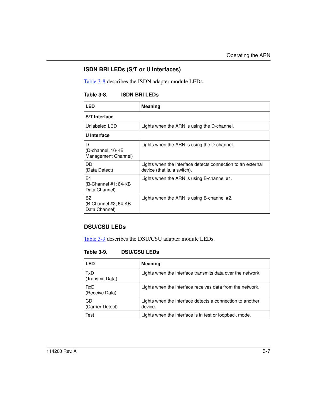
ISDN BRI LEDs (S/T or U Interfaces)
Table 3-8 describes the ISDN adapter module LEDs.
Table | ISDN BRI LEDs | |
|
|
|
LED |
| Meaning |
|
|
|
S/T Interface |
|
|
|
|
|
Unlabeled LED |
| Lights when the ARN is using the |
|
|
|
U Interface |
|
|
|
|
|
D |
| Lights when the ARN is using the |
| ||
Management Channel) |
| |
|
|
|
DD |
| Lights when the interface detects connection to an external |
(Data Detect) |
| device (that is, a switch). |
|
|
|
B1 |
| Lights when the ARN is using |
| ||
Data Channel) |
|
|
|
|
|
B2 |
| Lights when the ARN is using |
| ||
Data Channel) |
|
|
|
|
|
DSU/CSU LEDs
Table 3-9 describes the DSU/CSU adapter module LEDs.
Table | DSU/CSU LEDs | |
|
|
|
LED |
| Meaning |
|
|
|
TxD |
| Lights when the interface transmits data over the network. |
(Transmit Data) |
|
|
|
|
|
RxD |
| Lights when the interface receives data from the network. |
(Receive Data) |
|
|
|
|
|
CD |
| Lights when the interface detects a connection to another |
(Carrier Detect) |
| device. |
|
|
|
Test |
| Lights when the interface is in test or loopback mode. |
|
|
|
114200 Rev. A |