Technical Specifications
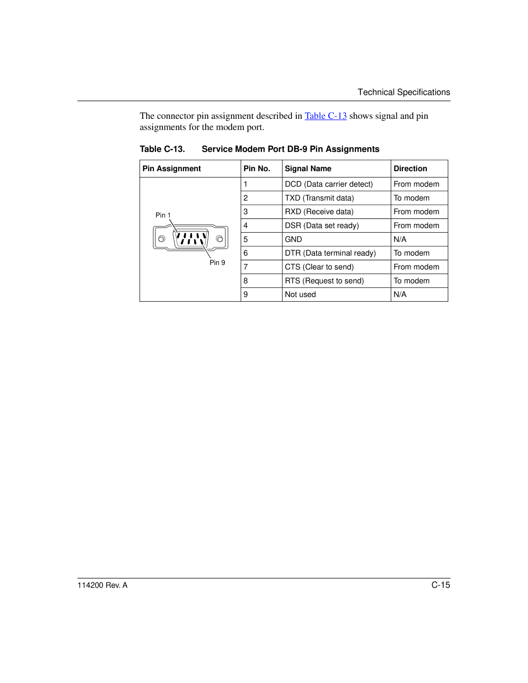
The connector pin assignment described in Table
Table C-13. Service Modem Port DB-9 Pin Assignments
Pin Assignment |
| Pin No. | Signal Name | Direction |
|
|
|
|
|
|
| 1 | DCD (Data carrier detect) | From modem |
|
|
|
|
|
|
| 2 | TXD (Transmit data) | To modem |
|
|
|
|
|
Pin 1 |
| 3 | RXD (Receive data) | From modem |
|
|
|
| |
|
| 4 | DSR (Data set ready) | From modem |
|
|
|
|
|
|
| 5 | GND | N/A |
|
|
|
|
|
|
| 6 | DTR (Data terminal ready) | To modem |
| Pin 9 |
|
|
|
| 7 | CTS (Clear to send) | From modem | |
|
| |||
|
|
|
|
|
|
| 8 | RTS (Request to send) | To modem |
|
|
|
|
|
|
| 9 | Not used | N/A |
|
|
|
|
|
114200 Rev. A |