Installing and Operating BayStack ARN Routers
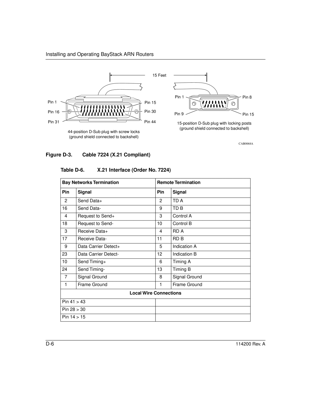
15 Feet
Pin 1 | Pin 15 |
Pin 16 | Pin 30 |
Pin 31 | Pin 44 |
| |
| (ground shield connected to backshell) |
Figure D-3. Cable 7224 (X.21 Compliant)
Pin 1 ![]()
![]() Pin 8
Pin 8
Pin 9 | Pin 15 |
CAB0068A
Table | X.21 Interface (Order No. 7224) |
| ||
|
|
| ||
Bay Networks Termination | Remote Termination | |||
|
|
|
|
|
Pin | Signal |
| Pin | Signal |
|
|
|
| |
2 | Send Data+ | 2 | TD A | |
|
|
|
| |
16 | Send Data- | 9 | TD B | |
|
|
|
| |
4 | Request to Send+ | 3 | Control A | |
|
|
|
| |
18 | Request to Send- | 10 | Control B | |
|
|
|
| |
3 | Receive Data+ | 4 | RD A | |
|
|
|
| |
17 | Receive Data- | 11 | RD B | |
|
|
|
| |
9 | Data Carrier Detect+ | 5 | Indication A | |
|
|
|
| |
23 | Data Carrier Detect- | 12 | Indication B | |
|
|
|
| |
10 | Send Timing+ | 6 | Timing A | |
|
|
|
| |
24 | Send Timing- | 13 | Timing B | |
|
|
|
| |
7 | Signal Ground | 8 | Signal Ground | |
|
|
|
| |
1 | Frame Ground | 1 | Frame Ground | |
|
|
|
|
|
Local Wire Connections
Pin 41 > 43
Pin 28 > 30
Pin 14 > 15
114200 Rev. A |