Specifications
External Device I/O Terminals
External Device Input Terminals (IN+, IN–)
The external device input terminals consist of a + terminal and a
Connect any sensors and switches to terminals with electrically separate GND terminals and power supplies.
External Device Output Terminals (OUT A, OUT B)
The external device output terminals consist two terminals (OUT A and OUT B). There is no distinction between + and
*External input status can be checked and external output status can be controlled using Admin Viewer (→
Loads connected to the output terminals should be within the following ratings:
Rating across the output terminals: Up to 50 V DC
|
| Continuous load current: 100 mA |
|
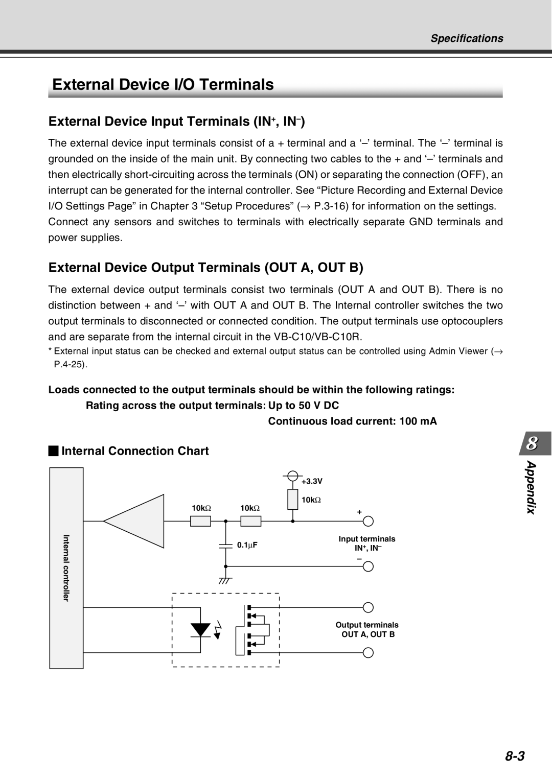
Internal Connection Chart |
|
| Appendix |
10kΩ | 10kΩ | + | |
|
| +3.3V |
|
|
| 10kΩ |
|
Internal |
| – |
|
| 0.1∝F | Input terminals |
|
| IN+, IN– |
| |
controller |
|
|
|
|
| Output terminals |
|
|
| OUT A, OUT B |
|