Using the Still Picture Recording Function Linked to an External Device
By combining various sensors and switches to operate according to External Device Input settings, it is possible to build a monitoring system that responds to external events. Still pictures are recorded in the
Sample Application Combining a Door-opening Sensor
This is a monitoring system in which the
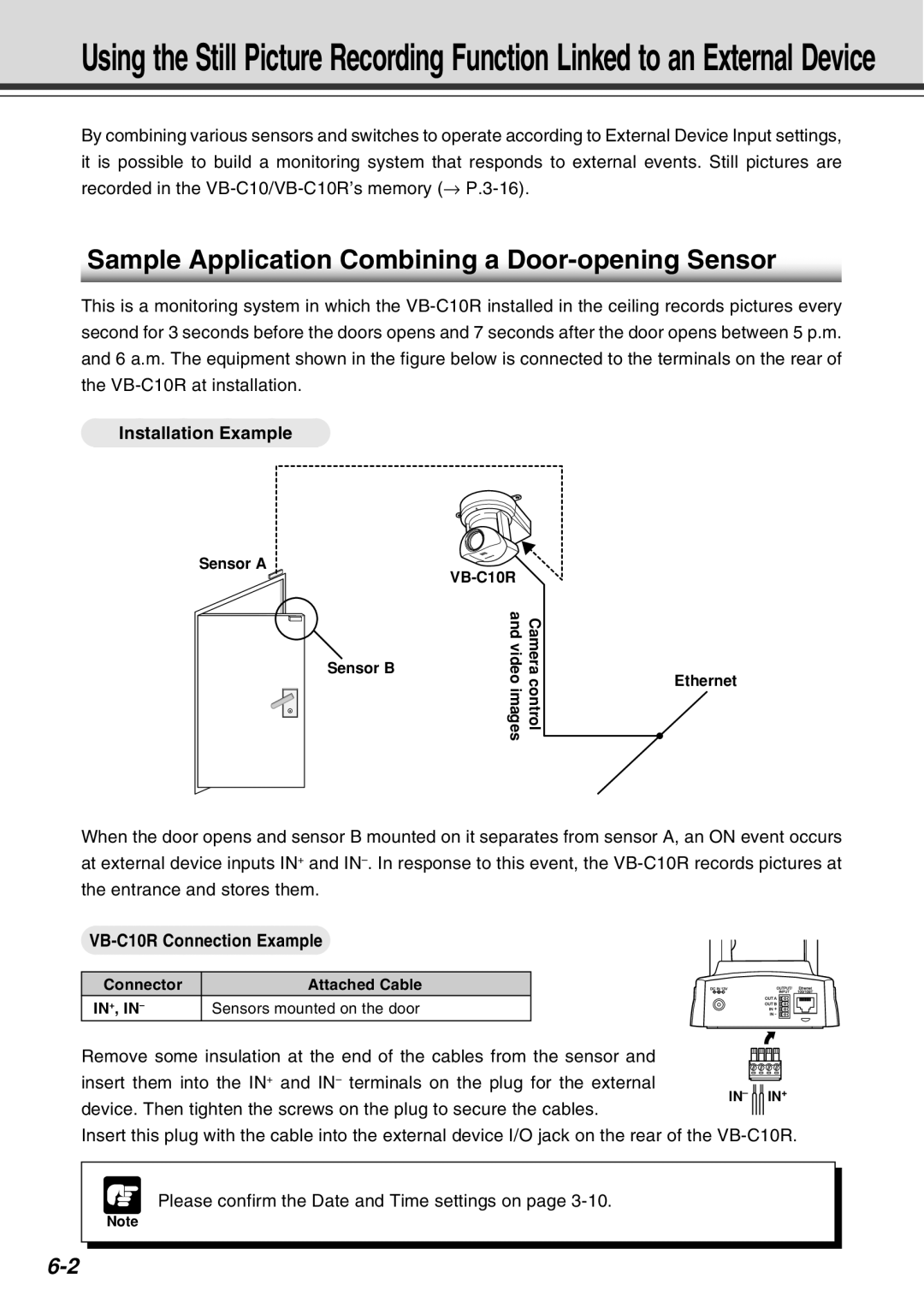
Installation Example
Sensor A
Cameracontrol | |
and videoimages | |
Sensor B |
|
Ethernet
When the door opens and sensor B mounted on it separates from sensor A, an ON event occurs at external device inputs IN+ and
VB-C10R Connection Example
Connector | Attached Cable |
IN+, IN– | Sensors mounted on the door |
Remove some insulation at the end of the cables from the sensor and
insert them into the IN+ and IN– terminals on the plug for the external
IN– IN+
device. Then tighten the screws on the plug to secure the cables.
Insert this plug with the cable into the external device I/O jack on the rear of the
Please confirm the Date and Time settings on page
Note