Before Using the
Connecting the Components
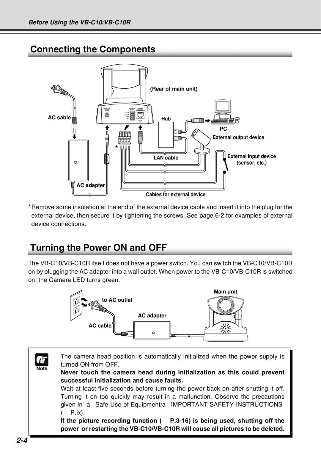
(Rear of main unit)
AC cable | Hub |
PC
External output device
*
LAN cable | External input device |
| (sensor, etc.) |
![]() AC adapter
AC adapter
Cables for external device
*Remove some insulation at the end of the external device cable and insert it into the plug for the external device, then secure it by tightening the screws. See page
Turning the Power ON and OFF
The
Note
Main unit
to AC outlet
AC adapter
AC cable
● The camera head position is automatically initialized when the power supply is turned ON from OFF.
● Never touch the camera head during initialization as this could prevent successful initialization and cause faults.
●Wait at least five seconds before turning the power back on after shutting it off. Turning it on too quickly may result in a malfunction. Observe the precautions given in “a Safe Use of Equipment/a IMPORTANT SAFETY INSTRUCTIONS” (→ P.ix).
●If the picture recording function (→