Chapter 3 Summary of Power and Cooling System Features
Cisco ICS 7750 Chassis, Backplane, and Fan Tray
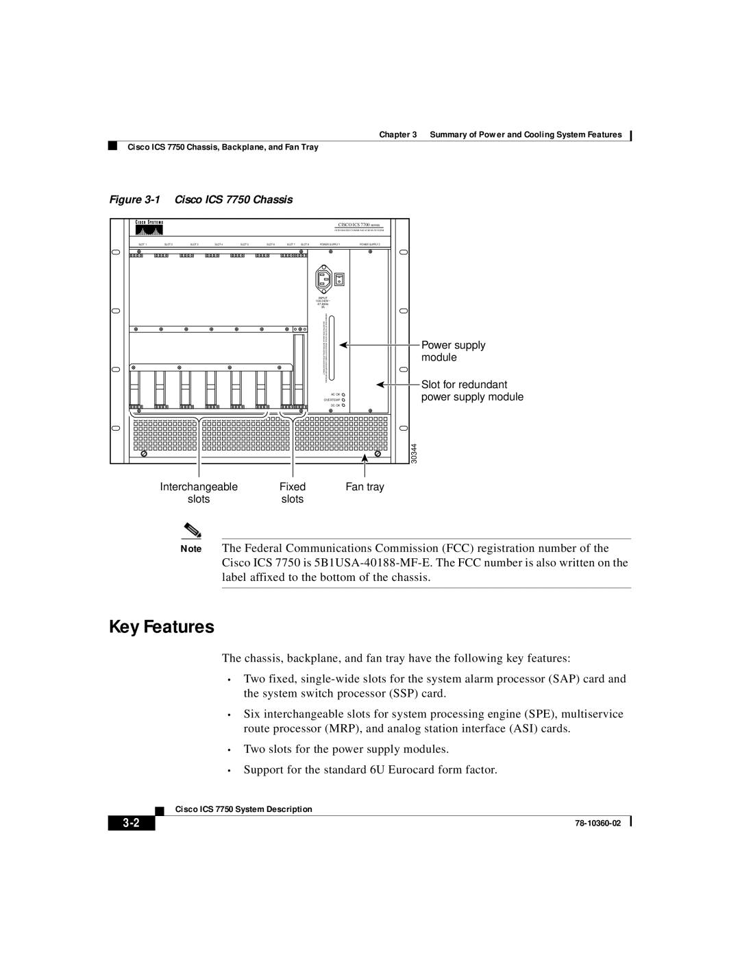
Figure 3-1 Cisco ICS 7750 Chassis
|
|
|
|
|
|
|
| CISCO ICS 7700 SERIES | |
|
|
|
|
|
|
|
| INTEGRATED COMMUNICATIONS SYSTEM | |
SLOT 1 | SLOT 2 | SLOT 3 | SLOT 4 | SLOT 5 | SLOT 6 | SLOT 7 SLOT 8 | POWER SUPPLY 1 | POWER SUPPLY 2 | |
|
|
|
|
|
|
| INPUT |
| |
|
|
|
|
|
|
|
| ||
|
|
|
|
|
|
|
| ||
|
|
|
|
|
|
| 3A |
|
|
|
|
|
|
|
|
| SEE INSTRUCTION MANUAL | WARNING! RISK OF ELECTRIC SHOCK, | Power supply |
|
|
|
|
|
|
| BEFORE INSTALLATION AND DISCONNECT | REMOVE BOTH POWER CORDS BEFORE SERVICING | |
|
|
|
|
|
|
| module | ||
|
|
|
|
|
|
| Slot for redundant | ||
|
|
|
|
|
|
|
|
| |
|
|
|
|
|
|
|
| AC OK | power supply module |
|
|
|
|
|
|
| OVERTEMP | ||
|
|
|
|
|
|
|
| DC OK |
|
|
|
|
|
|
|
|
|
| 30344 |
| Interchangeable |
|
| Fixed |
|
| Fan tray | ||
|
| slots |
|
|
| slots |
|
|
|
Note The Federal Communications Commission (FCC) registration number of the Cisco ICS 7750 is
Key Features
The chassis, backplane, and fan tray have the following key features:
•Two fixed,
•Six interchangeable slots for system processing engine (SPE), multiservice route processor (MRP), and analog station interface (ASI) cards.
•Two slots for the power supply modules.
•Support for the standard 6U Eurocard form factor.
Cisco ICS 7750 System Description
|
| |
|