Options
5.3.2Cabinet Installation
Parallel system composed of two or more UPS modules using parallel cabinet
The UPS modules that will form the parallel system should be placed
The parallel cabinet should be placed in the middle of the system.
5.3.3Preliminary Checks
Each UPS module should have the same firmware and the same hardware version. Refer to the instructions in 5.3.1 - Conditions for Parallel System.
5.3.4Power Cables
Wiring of power cables is similar to that of a single module system (See 3.1 - Power Cabling). The bypass sources of all modules should be the same, and the outputs should be connected altogether correctly.
Power cables are
NOTE
The system input and/or output circuit breaker is to be
NOTE
The length and specifications of power cables including the bypass input cables and UPS output cables should be the same, thus the load can be shared evenly in bypass mode.
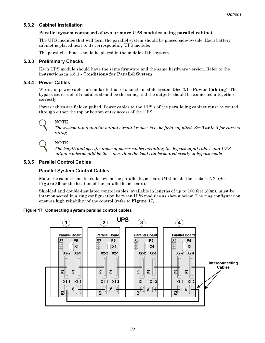
5.3.5Parallel Control Cables Parallel System Control Cables
Make the connections listed below on the parallel logic board (M3) inside the Liebert NX. (See Figure 30 for the location of the parallel logic board):
Shielded and
Figure 17 Connecting system parallel control cables
1 |
| 2 | UPS | 3 |
|
| 4 |
|
|
|
|
|
| ||||
Parallel Board | Parallel Board | Parallel Board | Parallel Board | |||||
X3 | P5 | X3 | P5 | X3 | P5 | X3 |
| P5 |
| X4 |
| X4 |
| X4 |
|
| X4 |
|
|
|
|
|
|
|
| Interconnecting |
P2 |
| P2 |
| P2 |
| P2 |
| Cables |
P1 | P1 | P1 |
| P1 | ||||
P3 | P4 | P3 | P4 | P3 | P4 | P3 |
| P4 |
|
|
|
| 33 |
|
|
|
|