Installation Drawings
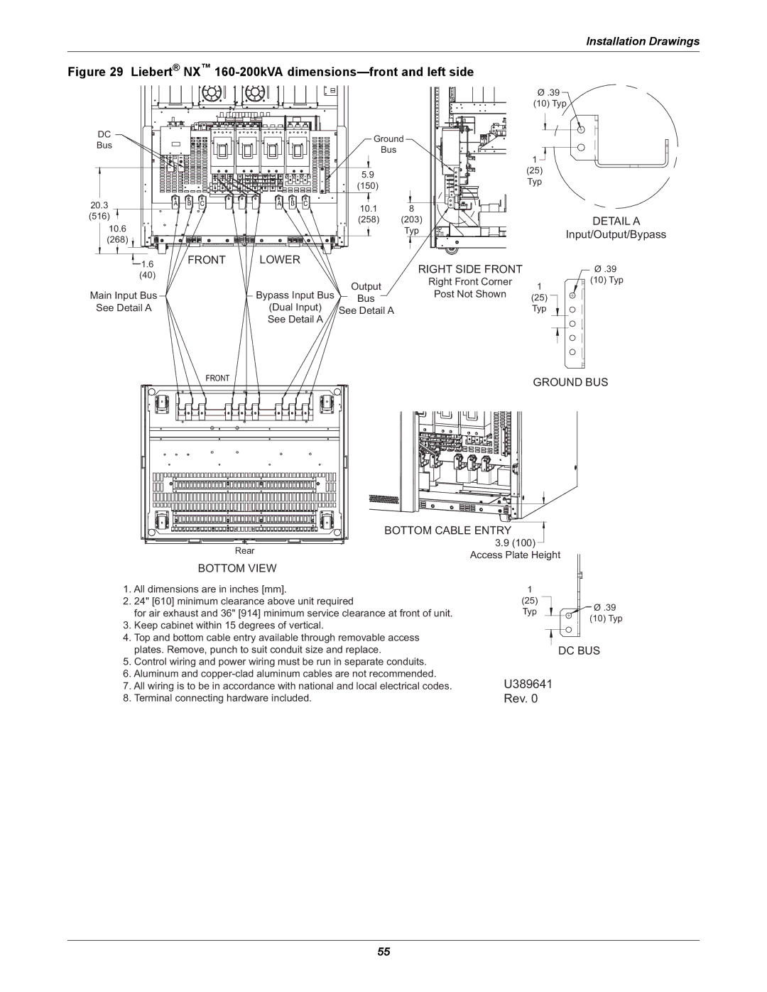
Figure 29 | Liebert® NX™ |
| ||||
|
|
|
|
|
| Ø .39 |
|
|
|
|
|
| (10) Typ |
DC |
|
|
| Ground |
| |
Bus |
|
|
|
| ||
|
|
| Bus |
|
| |
|
|
|
|
| 1 | |
|
|
|
|
|
| |
|
|
|
| 5.9 |
| (25) |
|
|
|
|
| Typ | |
|
|
|
| (150) |
| |
|
|
|
|
|
| |
20.3 |
|
|
| 10.1 | 8 |
|
(516) |
|
|
|
| ||
|
|
| (258) | (203) | DETAIL A | |
10.6 |
|
|
| |||
|
|
|
| Typ | Input/Output/Bypass | |
(268) |
|
|
|
| ||
|
|
|
|
|
| |
| 1.6 | FRONT | LOWER |
| RIGHT SIDE FRONT | Ø .39 |
| (40) |
|
|
| ||
|
|
| Output | Right Front Corner | (10) Typ | |
|
|
|
| |||
Main Input Bus |
| Bypass Input Bus | Post Not Shown | 1 | ||
| Bus | (25) | ||||
See Detail A |
| (Dual Input) | See Detail A |
| Typ | |
|
|
| See Detail A |
|
|
|
|
|
|
|
|
| GROUND BUS |
|
|
|
| BOTTOM CABLE ENTRY |
| |
|
|
| Rear |
| 3.9 (100) | |
|
|
|
| Access Plate Height | ||
|
|
|
|
| ||
BOTTOM VIEW
1. All dimensions are in inches [mm]. | 1 |
| |
2. | 24" [610] minimum clearance above unit required | (25) | Ø .39 |
| for air exhaust and 36" [914] minimum service clearance at front of unit. | Typ | |
| (10) Typ | ||
3. | Keep cabinet within 15 degrees of vertical. |
| |
|
| ||
4. Top and bottom cable entry available through removable access |
|
| |
| plates. Remove, punch to suit conduit size and replace. |
| DC BUS |
5.Control wiring and power wiring must be run in separate conduits.
6.Aluminum and
7. All wiring is to be in accordance with national and local electrical codes. | U389641 |
8. Terminal connecting hardware included. | Rev. 0 |
55