Installation Drawings
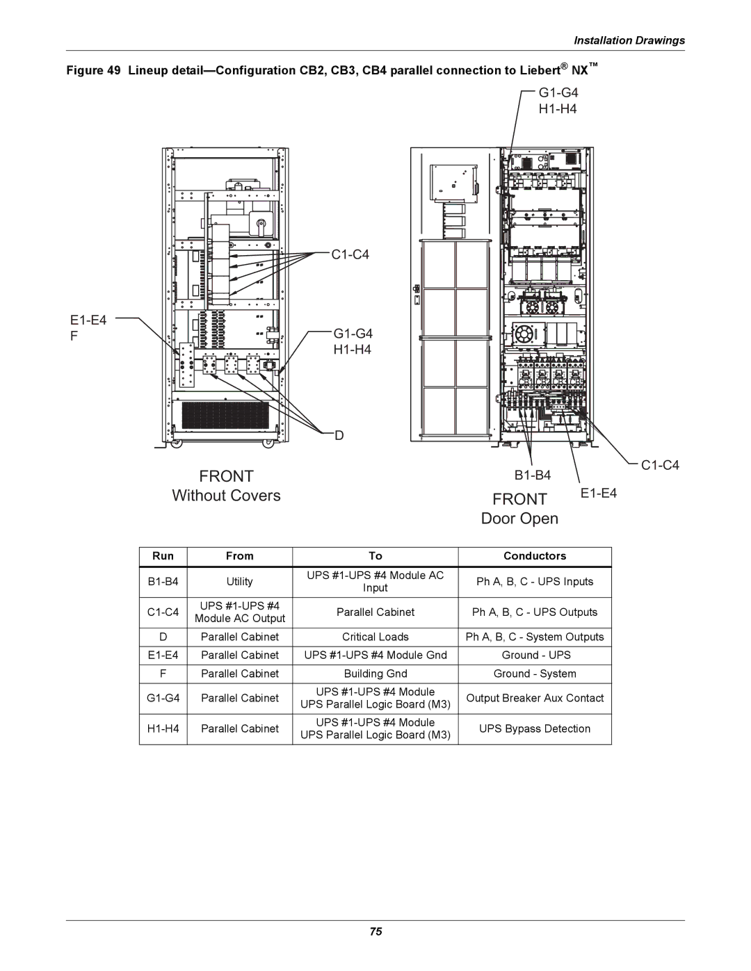
Figure 49 Lineup detail—Configuration CB2, CB3, CB4 parallel connection to Liebert® NX™
F
D |
FRONT |
Without Covers |
| |
| |
| |
FRONT | |
Door Open |
|
Run | From | To | Conductors | |
|
|
|
| |
Utility | UPS | Ph A, B, C - UPS Inputs | ||
Input | ||||
|
|
| ||
UPS | Parallel Cabinet | Ph A, B, C - UPS Outputs | ||
Module AC Output | ||||
|
|
| ||
D | Parallel Cabinet | Critical Loads | Ph A, B, C - System Outputs | |
|
|
|
| |
Parallel Cabinet | UPS | Ground - UPS | ||
|
|
|
| |
F | Parallel Cabinet | Building Gnd | Ground - System | |
|
|
|
| |
Parallel Cabinet | UPS | Output Breaker Aux Contact | ||
UPS Parallel Logic Board (M3) | ||||
|
|
| ||
Parallel Cabinet | UPS | UPS Bypass Detection | ||
UPS Parallel Logic Board (M3) | ||||
|
|
|
75
