Options
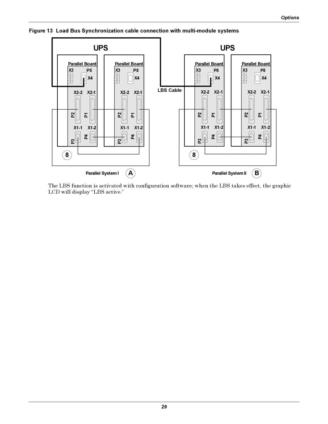
Figure 13 Load Bus Synchronization cable connection with multi-module systems
| UPS |
|
|
Parallel Board | Parallel Board | ||
X3 | P5 | X3 | P5 |
| X4 |
| X4 |
P2 | P1 | P2 | P1 |
P3 | P4 | P3 | P4 |
8 |
|
|
|
| Parallel System I | A | |
|
| UPS |
|
|
| Parallel Board | Parallel Board | ||
| X3 | P5 | X3 | P5 |
|
| X4 |
| X4 |
LBS Cable | ||||
| ||||
| P2 | P1 | P2 | P1 |
| ||||
| P3 | P4 | P3 | P4 |
| 8 |
|
|
|
|
| Parallel System II | B | |
The LBS function is activated with configuration software; when the LBS takes effect, the graphic LCD will display “LBS active.”
29
