Electrical Connections
3.3.3Battery Circuit Breaker Control Interface
J10 is the Battery Circuit Breaker (BCB) box interface.
Table 3 BCB control interface
Position | Name | Description | |
J10.1 | DRV | BCB Driver Signal | |
|
|
| |
J10.2 | FB | BCB Contact State | |
|
|
| |
J10.3 | GND | Power Ground | |
|
|
| |
J10.4 | OL | BCB | |
BCB interface is connected. (N.O.) | |||
|
|
NOTE
All auxiliary cables of terminal must be
3.3.4Output Dry Contacts
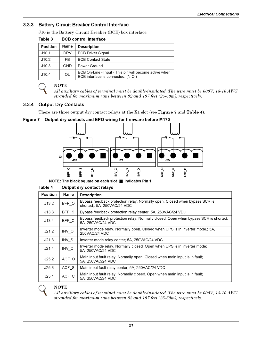
There are three output dry contact relays at the X1 slot (see Figure 7 and Table 4).
Figure 7 Output dry contacts and EPO wiring for firmware before M170
X1
J13
J21
J25
BFP C | BFP S | BFP O | INV C | INV S | INV O | ACF C | ACF S | ACF O |
NOTE: The black square on each slot ![]() indicates Pin 1.
indicates Pin 1.
Table 4 Output dry contact relays
Position | Name | Description | |
J13.2 | BFP_O | Bypass feedback protection relay. Normally open. Closed when bypass SCR is | |
shorted;. 5A, 250VAC/24 VDC | |||
|
| ||
J13.3 | BFP_S | Bypass feedback protection relay center; 5A, 250VAC/24 VDC | |
|
|
| |
J13.4 | BFP_C | Bypass feedback protection relay. Normally closed. Open when bypass SCR is shorted; | |
5A, 250VAC/24 VDC | |||
|
| ||
J21.2 | INV_O | Inverter mode relay. Normally open. Closed when UPS is in inverter mode.; 5A, | |
250VAC/24 VDC | |||
|
| ||
J21.3 | INV_S | Inverter mode relay center; 5A, 250VAC/24 VDC | |
|
|
| |
J21.4 | INV_C | Inverter mode relay. Normally closed. Open when UPS is in inverter mode; | |
5A, 250VAC/24 VDC | |||
|
| ||
J25.2 | ACF_O | Main input fault relay. Normally open. Closed when main input is in fault; | |
5A, 250VAC/24 VDC | |||
|
| ||
J25.3 | ACF_S | Main input fault relay center; 5A, 250VAC/24 VDC | |
|
|
| |
J25.4 | ACF_C | Main input fault relay. Normally closed. Open when main input is in fault; | |
5A, 250VAC/24 VDC | |||
|
|
NOTE
All auxiliary cables of terminal must be
21