Installation Drawings
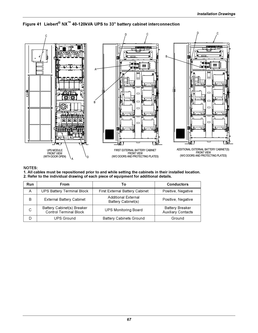
Figure 41 Liebert® NX™ 40-120kVA UPS to 33" battery cabinet interconnection
NOTES:
1.All cables must be repositioned prior to and while setting the cabinets in their installed location.
2.Refer to the individual drawing of each piece of equipment for additional details.
Run | From | To | Conductors | |
|
|
|
| |
A | UPS Battery Terminal Block | First External Battery Cabinet | Positive, Negative | |
|
|
|
| |
B | External Battery Cabinet | Additional External | Positive, Negative | |
Battery Cabinet(s) | ||||
|
|
| ||
C | Battery Cabinet(s) Breaker | UPS Monitoring Board | Battery Breaker | |
Control Terminal Block | Auxiliary Contacts | |||
|
| |||
D | UPS Ground | Battery Cabinets Ground | Ground | |
|
|
|
|
67
