Operating Instructions
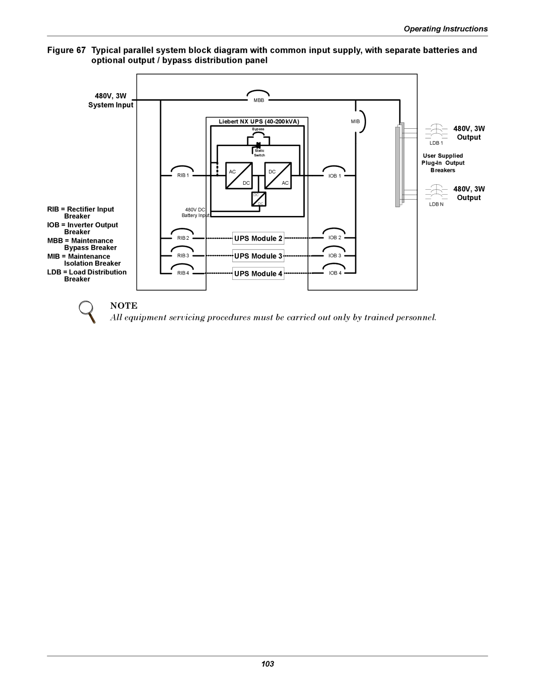
Figure 67 Typical parallel system block diagram with common input supply, with separate batteries and optional output / bypass distribution panel
480V, 3W
System Input
MBB
RIB = Rectifier Input
Breaker
IOB = Inverter Output
Breaker
MBB = Maintenance
Bypass Breaker
MIB = Maintenance
Isolation Breaker
LDB = Load Distribution
Breaker
| Liebert NX UPS | |
|
| Bypass |
|
| Static |
|
| Switch |
RIB 1 | AC | DC |
|
| |
| DC | AC |
|
| DC |
|
| DC |
480V DC |
|
|
Battery Input |
|
|
RIB 2 ![]()
![]() UPS Module 2
UPS Module 2![]()
RIB 3 ![]()
![]() UPS Module 3
UPS Module 3![]()
RIB 4 ![]()
![]() UPS Module 4
UPS Module 4![]()
MIB
IOB 1
IOB 2
IOB 3
IOB 4
480V, 3W Output
LDB 1
User Supplied
Breakers
480V, 3W Output
LDB N
NOTE
All equipment servicing procedures must be carried out only by trained personnel.
