Audio Input and Output (Audio Models)
By default, the audio ties follow the video ties. Audio breakaway ties select from any one of the audio input sources and route it separately from its corresponding video source (see Example 3: Remove a tie from a set of ties on page 45). You can also use an SIS command (see page 95), the Matrix Switchers Control Program (see page 113), or the HTML pages (see Set and View Ties Page on page 142).
Captive Screw Connector Models (all Except MAV Plus 128 AV RCA)
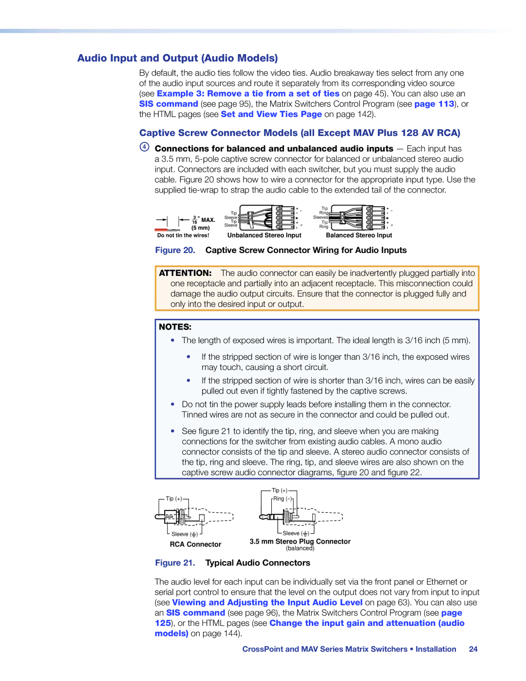
DConnections for balanced and unbalanced audio inputs — Each input has a 3.5 mm,
Tip | L | Tip | L |
Ring | |||
Sleeve |
| Sleeves |
|
Tip |
| Tip |
|
Sleeve | R | Ring | R |
Do not tin the wires! | Unbalanced Stereo Input | Balanced Stereo Input |
Figure 20. Captive Screw Connector Wiring for Audio Inputs
ATTENTION: The audio connector can easily be inadvertently plugged partially into one receptacle and partially into an adjacent receptacle. This misconnection could damage the audio output circuits. Ensure that the connector is plugged fully and only into the desired input or output.
NOTES:
•The length of exposed wires is important. The ideal length is 3/16 inch (5 mm).
•If the stripped section of wire is longer than 3/16 inch, the exposed wires may touch, causing a short circuit.
•If the stripped section of wire is shorter than 3/16 inch, wires can be easily pulled out even if tightly fastened by the captive screws.
•Do not tin the power supply leads before installing them in the connector. Tinned wires are not as secure in the connector and could be pulled out.
•See figure 21 to identify the tip, ring, and sleeve when you are making connections for the switcher from existing audio cables. A mono audio connector consists of the tip and sleeve. A stereo audio connector consists of the tip, ring and sleeve. The ring, tip, and sleeve wires are also shown on the captive screw audio connector diagrams, figure 20 and figure 22.
| Tip (+) | |
Tip (+) | Ring | |
Sleeve ( ) | Sleeve ( ) | |
RCA Connector | 3.5 mm Stereo Plug Connector | |
(balanced) | ||
|
Figure 21. Typical Audio Connectors
The audio level for each input can be individually set via the front panel or Ethernet or serial port control to ensure that the level on the output does not vary from input to input (see Viewing and Adjusting the Input Audio Level on page 63). You can also use an SIS command (see page 96), the Matrix Switchers Control Program (see page
125), or the HTML pages (see Change the input gain and attenuation (audio models) on page 144).
CrossPoint and MAV Series Matrix Switchers • Installation 24