User Guide
Safety Instructions English
Safety Instructions
FCC Class a Notice
Software Commands
Specifications Availability
Conventions Used in this Guide
Notifications
Contents
Matrix Software
Programming Guide
Html Operation
Ethernet Connection
About this Guide
About the Crosspoint and MAV Matrix Switchers
Extron CrossPoint Ultra 128 HVA
CrossPoint and MAV Series Matrix Switchers Introduction
CrossPoint and MAV Series Matrix Switchers Introduction
CrossPoint Ultra Switchers
MAV Plus Switchers
CrossPoint 450 Plus Switchers
MAV 1616 Plus 16 inputs by 16 outputs
Features
Definitions
Bandwidth
Dsvp Data Display
Tie any input to any or all outputs
CrossPoint and MAV Series Matrix Switchers Introduction
Installation the switcher and make all connections
Setup and Installation Checklist
Get ready
Ancillary operations
Rear Panel Views
CrossPoint 450 Plus 3232 HVA Matrix Switcher
CrossPoint Ultra 1616 HVA Matrix Switcher
MAV Plus 3232 SVA Matrix Switcher
MAV Plus 1616 Matrix Switchers with Various Formats
MAV Plus 1616 HDA Matrix Switcher
MAV Plus 128 AV RCA Matrix Switcher
Rgbhv CrossPoint switchers
Rear Panel Connections
Video Input and Output Video Models
CrossPoint Ultra
MAV Plus Component/HDTV Video Connections
Video MAV Plus switchers
MAV Plus Composite Video Connections
MAV Plus S-video Connections
Sync Termination Switches
Sync Termination Switches CrossPoint
Audio Input and Output Audio Models
Captive Screw Connector Wiring for Audio Inputs
Captive Screw Connector Wiring for Audio Output
RCA connector model MAV Plus 128 AV RCA
RS-232/RS-422
Remote RS-232/RS-422 Connector
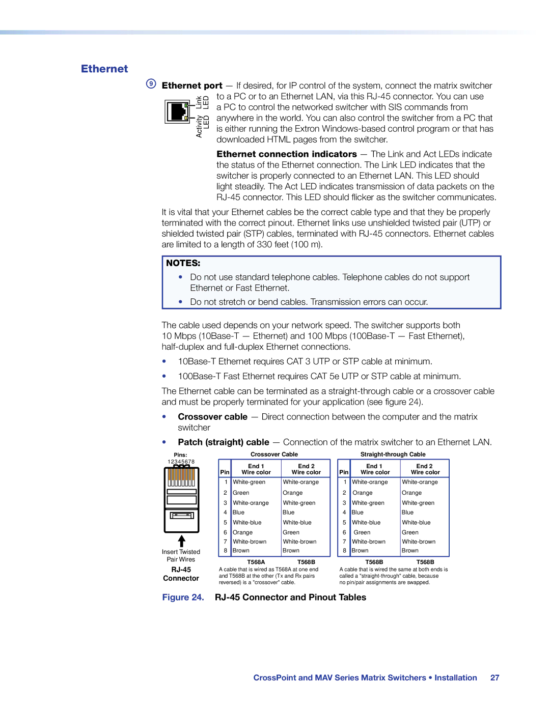
Ethernet
Ethernet
External Sync MAV Plus Video Models
Reset Button
Multiple Device External Sync Connection Example
Power
Front Panel Configuration Port
Front Panel Configuration Port
Operation
Front Panel Controls and Indicators
Front panel, CrossPoint Ultra 128 HVA
Comparison of Front Panels of Models
Crosspoint 450 Plus Series
CrossPoint
Input and Output Buttons
CrossPoint and MAV Series Matrix Switchers Operation
Audio
Control Buttons
CrossPoint and MAV Series Matrix Switchers Operation
Controls
Power LEDs 2412 and Larger Models Only
Primary and Redundant Power Supply LEDs
Button Icons
Definitions
Front Panel Operations
Front Panel Security Lockouts
Creating a Configuration
Select an input Press and release the input 5 button
Example 1 Create a set of video and audio ties
Example 2 Add a video tie to a set of video and audio ties
Final Configuration, Example
Example 3 Remove a tie from a set of ties
4 5 6 7 8 15
Viewing the Configuration
Button lights red
18 19 20 21 22 23 24
Or background
O Grouping of Incompatible Video Formats
Grouping
Press the Preset button to select group
Press the Enter button to select group
Press the View button to select group
Assign inputs and outputs to group
Example 5 Grouping inputs and outputs
Press and release the Input 5 through 8 buttons
Example 6 Setting the RGB delay for an output
Setting RGB Delay CrossPoint Switchers
3 4 5 6 7 8 15 23 24 31
CrossPoint or MAV Plus 1600 Preset Locations
Using Presets
Seconds All input buttons with assigned Presets light
Example 7 Saving a preset
4 15
Example 8 Recalling a preset
Muting and Unmuting Video and Audio Outputs
Select View-only
Example 9 Muting and unmuting an audio output
Mute outputs one at a time
Audio Gain and Attenuation
Viewing and Adjusting the Input Audio Level Audio Models
Output Button Audio Gain and Attenuation Display
Matrix sizes
Select an Input
Example 10 Viewing and adjusting an input audio level
Level Display on a 8-output-button Switcher
Exit Audio mode Press and release the Audio button
Viewing and Adjusting the Analog Output Volume Audio Models
Reading the displayed volume
Audio Volume Display
CrossPoint and MAV Series Matrix Switchers Operation
10 11 13 14 15
10 11
Volume Display on a 16-input-button Switcher
Selecting Lock mode 2 or toggling between mode 2 and mode
Setting the Front Panel Locks Executive Modes
System Reset
Performing a System Reset from the Front Panel
Selecting the Rear Panel Remote Port Protocol and Baud Rate
Background Illumination
Switcher model or Reset Resets MAV Plus switcher matrix size
Rear Panel Reset Operations
Mode Activation Result
Reset Mode Comparison and Summary
Soft System Resets
Performing Soft System Resets Resets 3, 4,
Whole Switcher and Absolute Resets
Performing Soft Resets
Hard Reset
Performing a Hard Reset All Models
Troubleshooting
Plasma Display S-video Problem CrossPoint Switchers
Optimizing the Audio Audio Models
Worksheet Example 1 System Equipment
Configuration Worksheets
Worksheet example 2 Daily Configuration
Worksheet Example 2 Daily Configuration
Worksheet Example 3 Test Configuration
Worksheet Example 3 Test Configuration
Output destinations
Button switchers configuration worksheet
Audio
Programming Guide
Serial Ports
Front Panel Configuration Port
Ethernet LAN Port
Rear Panel RS-232/RS-422 Port
Connection Timeouts
Default IP addresses
Establishing a Connection
Number of Connections
Host-to-Switcher Instructions
Switcher-initiated Messages
Using Verbose Mode
Switcher Error Responses
Using the Command and Response Tables
Command and Response Table for SIS Commands
Symbol Definitions
Command Function SIS Command Response Additional description
Command and Response Table for SIS Commands
Read ties
Audio output volume
Audio Volume Adjustment Settings
Audio mutes
View ties, gain, volume, mutes, and presets
EX*X@*1VC NX!n+1...X!n+15Vid
$LS
EX11X12...X1nI GriX11X12X13...X1n
Names
Resets
Information requests
View and erase file directory
X4! =
X5$ =
IP and Remote port setup commands
CrossPoint 450 Plus
Special Characters
Matrix Switchers Control Program
Ethernet protocol settings
Software Operation via Ethernet
Software Operation via a Serial Port
Installing the Software
Comm Port Selection Window
Using the Matrix Switcher Control Software
Address and Password Entry
Sample Program Window Icons Assigned and Ties Created
Control Program IP Setting/Options Window
IP Settings/Options window
Subnet mask
Use Dhcp check box
Sync Time to PC button
Mail Server Domain Name field
Mail Server IP Address field
Updating the Firmware
Downloading Firmware Upgrade Files
Ethernet-connected firmware upload
Serial-port-connected firmware upload
Html Files List Window
Uploading Html Files
Windows Buttons, Drop Boxes, and Trash Can
Windows Menus
File menu
Status Window
Tools menu
Preferences menu
Audio-input Configuration selection
Master-Reset selection
Using Emulation Mode
Emulate Configuration Dialog Box
Using the Help System
Button-Label Generator Program
Installing the Button Label Generator Software
Extron Button-Label Generator Window
Using the Button-Label Generator Software
Html Operation
Download the Startup
Enter Network Password Dialog Box
Status Tab
System Status
Not displayed for the CrossPoint or MAV
Configuration Tab
Dsvp Page CrossPoint Switchers
System Settings
Unit Name field
IP Settings fields
Date/Time Settings Fields
Date/Time Settings fields
Resetting a password
Passwords
Mail IP Address field
Email Settings
Deselecting Smtp authorization
Firmware Upgrade
Firmware Upgrade
File Management
File Management Tab
Control Tab
Set and View Ties
Amber buttons indicate video and audio ties
RGB and Audio Settings
RGB and Audio Settings
Input Selection Drop Box
Change the input gain and attenuation audio models
Mute and unmute one or all outputs
Change the RGB delay CrossPoint switchers
RGB Delay Drop Box
Change the output volume level audio models
Number Output Steps Attenuation Volume
Global Presets
Saving a preset
Recalling a preset
Default IP Address
Ethernet Link
Ethernet Connection
Pinging to Determine the Web IP Address
Pinging to Determine the Extron IP Address
Ping with New Address
Connecting as a Telnet Client
Telnet Tips
Open
Analog echo
Escape character and Esc key
Set carriage return-line feed
Close
Gateways
Subnetting a Primer
Analog and Remote Devices
IP Addresses and Octets
Determining Whether Devices Are on the Same Subnet
Subnet Masks and Octets
Unmasked octets are compared indicated by ? in figure
Masked octets are not compared indicated by X in figure
Reference Information
Mounting the Switcher
Mounting Instructions
UL Guidelines
Removing and Installing Button Labels
Installing Labels in the Buttons
Making Labels from Paper Templates
Button Label Blanks
Extron Warranty