!CAUTION
1.Noise is generated from the drive, motor, and wiring. Take care that this noise does not cause malfunctions in peripheral sensors and equipment, otherwise accidents could occur.
(4)Control terminal arrangement, screw size, and tightening torque Figure
30A![]() 30B
30B ![]() 30C
30C ![]() FM
FM ![]() X1
X1 ![]() X2
X2 ![]() X3
X3 ![]() FWD
FWD ![]() REV
REV![]() CM
CM ![]() 11
11 ![]() 12
12 ![]() 13
13 ![]() C1
C1
Figure 2-3-7 Control terminal block arrangement
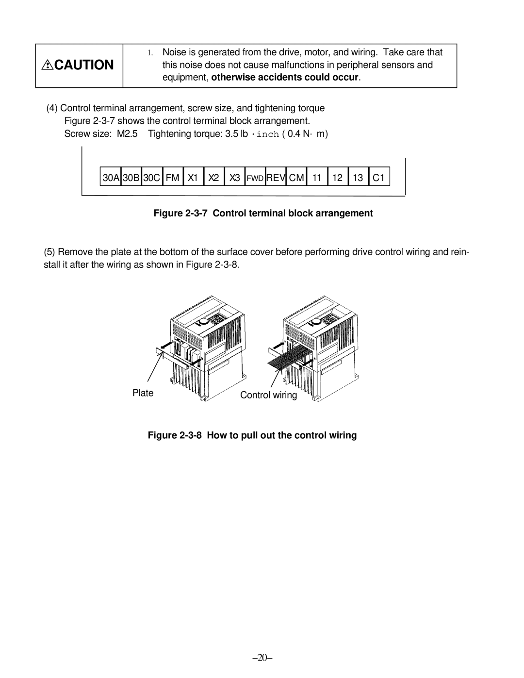
(5)Remove the plate at the bottom of the surface cover before performing drive control wiring and rein- stall it after the wiring as shown in Figure
Plate | Control wiring |