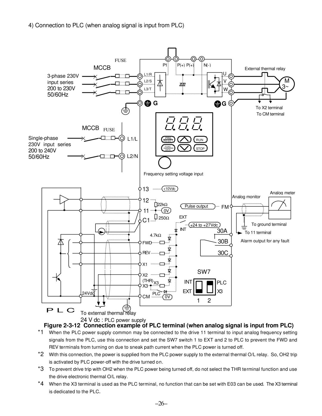
4) Connection to PLC (when analog signal is input from PLC)
FUSE
MCCB
200 to 230V
50/60Hz
L1/R
L2/S
L3/T
P1 | P(+) P(+) | |
|
| U |
|
| V |
|
| W |
External thermal relay
M |
3~ |
|
|
| G |
|
|
|
| G | To X2 terminal |
|
|
|
|
|
|
|
|
| |
|
|
|
|
|
|
|
|
| To CM terminal |
| MCCB FUSE |
|
|
|
|
|
|
|
|
L1/L |
| RESET |
| RUN |
|
|
| ||
|
|
|
| PRG |
|
|
|
|
|
230V input | series |
|
| FUNC |
| STOP |
|
|
|
200 to 240V |
|
|
| DATA |
|
|
|
| |
| L2/N |
|
|
|
|
|
|
| |
50/60Hz |
|
|
|
|
|
|
|
| |
|
| Frequency setting voltage input |
|
|
| ||||
|
| 13 |
| +10Vdc |
|
|
|
| Analog meter |
|
|
|
|
|
|
|
|
| |
|
| 12 |
|
|
|
|
|
| Analog monitor |
|
| 22kΩ | Pulse output |
|
| ||||
|
|
| FM |
| |||||
|
| 11 |
| 0V |
| ||||
|
|
|
|
|
|
|
| ||
|
|
|
| Ω | EXT |
|
|
|
|
|
| C1 | 250 |
|
|
|
|
| |
|
|
|
| +24 to +27Vdc | To ground terminal | ||||
|
|
|
|
| |||||
|
|
|
|
| INT |
|
| 30A | To 11 terminal |
|
| 4.7kΩ |
|
|
|
| |||
|
|
|
|
|
|
|
| ||
|
| FWD |
|
|
|
|
| 30B | Alarm output for any fault |
|
| REV |
|
|
|
|
| 30C |
|
|
| X1 |
|
|
|
|
|
|
|
|
| X2 |
|
|
| SW7 |
|
| |
|
|
|
|
|
|
|
|
| |
|
| (THR)X3 |
| INT |
|
| PLC |
| |
|
| X3 |
|
| EXT |
|
| X3 |
|
| 24Vdc | CM PLC |
|
|
|
| |||
| 0V |
| 1 | 2 |
|
| |||
|
|
|
|
|
|
|
| ||
| P L C To external thermal |
|
|
|
|
| relay | ||||
| 24 V dc : PLC power supply | ||||
*1 | Figure | ||||
When the PLC power supply common may be connected to the drive 11 terminal to input analog frequency setting | |||||
| signals from the PLC, use this connection and set the SW7 switch 1 to EXT and 2 to PLC to prevent the FWD and | ||||
| REV terminals from turning on due to sneak path current when the PLC power is turned off. | ||||
*2 | With this connection, the power is supplied from the PLC power supply to the external thermal O/L relay. So, OH2 trip | ||||
| is activated by PLC | ||||
*3 | To prevent drive trip with OH2 when the PLC power being turned off, do not select the THR terminal function and use | ||||
| the drive electronic thermal O/L relay. | ||||
*4 | When the X3 terminal is used as the PLC terminal, no function that can be set with E03 can be used. The X3 terminal | ||||
| is dedicated to the PLC. | ||||