2 Installation and Connection
Install this product at a place satisfying the conditions listed in Table
| Table | ||
Item |
| Specifications | |
Place | Indoor |
| |
Ambient temperature | |||
Ambient relative | 5 to 95%RH(No condensation allowed) | ||
humidity | |||
|
| ||
| The product must not be exposed to dust, direct sunlight, corro- | ||
| sive gas, inflammable gas, oil mist, vapor, or water drops. | ||
Atmosphere | There must be no salt in the atmosphere. | ||
| Condensation must not be caused by sudden changes in tem- | ||
| perature. |
| |
Altitude | 3300 feet (1000m) or less ( Air pressure : 86kPa to 106kPa ) | ||
| 3mm: | 2 to less than 9Hz | |
Vibration | 9.8 m/s2: 9 to less than 20Hz | ||
2 m/s2: | 20 to less than 55Hz | ||
| |||
| 1 m/s2: | 55 to less than 200Hz | |
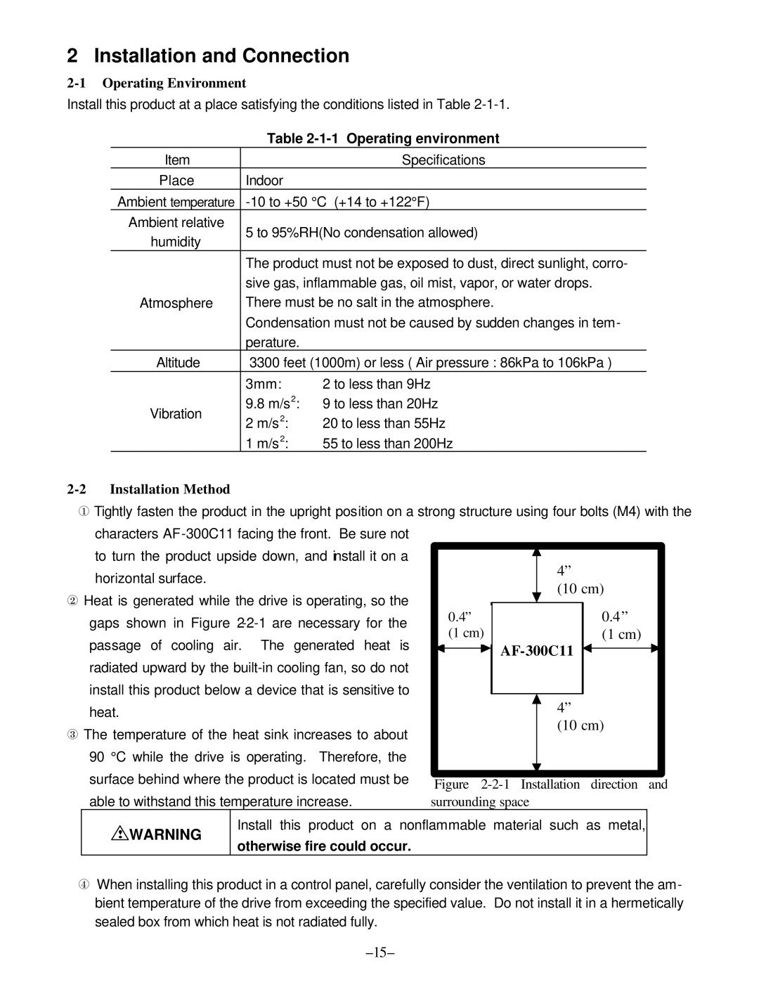
2-2 Installation Method
¬Tightly fasten the product in the upright position on a strong structure using four bolts (M4) with the characters
to turn the product upside down, and install it on a |
|
|
|
| 4” | |||
|
|
|
| |||||
horizontal surface. |
|
|
|
| ||||
|
|
|
| (10 cm) | ||||
- Heat is generated while the drive is operating, so the |
|
|
|
| ||||
|
|
|
|
|
|
| ||
gaps shown in Figure |
| 00.4”.4” |
|
|
|
| 0.4” | |
| (1 cm) |
|
|
|
| (1 cm) | ||
|
|
|
|
|
| |||
passage of cooling air. The generated heat is |
| (1 cm) |
|
|
| |||
|
|
|
|
|
| |||
|
|
|
|
| ||||
|
|
|
|
|
|
| ||
radiated upward by the |
|
|
|
|
|
|
| |
install this product below a device that is sensitive to |
|
|
|
|
|
|
| |
|
|
|
| 4” | ||||
heat. |
|
|
|
| ||||
|
|
|
| |||||
® The temperature of the heat sink increases to about |
|
|
|
| (10 cm) | |||
|
|
|
|
|
|
| ||
90 °C while the drive is operating. Therefore, the |
|
|
|
|
|
|
| |
surface behind where the product is located must be |
|
|
| |||
Figure | ||||||
|
|
| ||||
able to withstand this temperature increase. |
| surrounding space | ||||
! WARNING | Install this product | on a nonflammable material such as metal, |
| |||
otherwise fire could occur. |
|
|
| |||
|
|
|
| |||
¯When installing this product in a control panel, carefully consider the ventilation to prevent the am- bient temperature of the drive from exceeding the specified value. Do not install it in a hermetically sealed box from which heat is not radiated fully.