10 Options
10-1 Built-in Options
There is an optional
10-2 External Options
| Table |
|
|
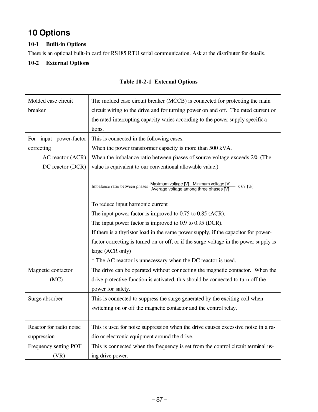
Molded case circuit | The molded case circuit breaker (MCCB) is connected for protecting the main |
breaker | circuit wiring to the drive and for turning power on and off. The rated current or |
| the rated interrupting capacity varies according to the power supply specific a- |
| tions. |
For input | This is connected in the following cases. |
correcting | When the power transformer capacity is more than 500 kVA. |
AC reactor (ACR) | When the imbalance ratio between phases of source voltage exceeds 2% (The |
DC reactor (DCR) | value is equivalent to our conventional allowable value.) |
| Maximum voltage [V] - Minimum voltage [V] |
| Imbalance ratio between phases = |
| Average voltage among three phases [V] |
| To reduce input harmonic current |
| The input power factor is improved to 0.75 to 0.85 (ACR). |
| The input power factor is improved to 0.9 to 0.95 (DCR). |
| If there is a thyristor load in the same power supply, if the capacitor for power- |
| factor correcting is turned on or off, or if the surge voltage in the power supply is |
| large (ACR only) |
| * The AC reactor is unnecessary when the DC reactor is used. |
Magnetic contactor | The drive can be operated without connecting the magnetic contactor. When the |
(MC) | drive protective function is activated, this should be connected to turn off the |
| power for safety. |
Surge absorber | This is connected to suppress the surge generated by the exciting coil when |
| switching on or off the magnetic contactor and the control relay. |
|
|
Reactor for radio noise | This is used for noise suppression when the drive causes excessive noise in a ra- |
suppression | dio or electronic equipment around the drive. |
Frequency setting POT | This is connected when the frequency is set from the control circuit terminal us- |
(VR) | ing drive power. |
- 87-