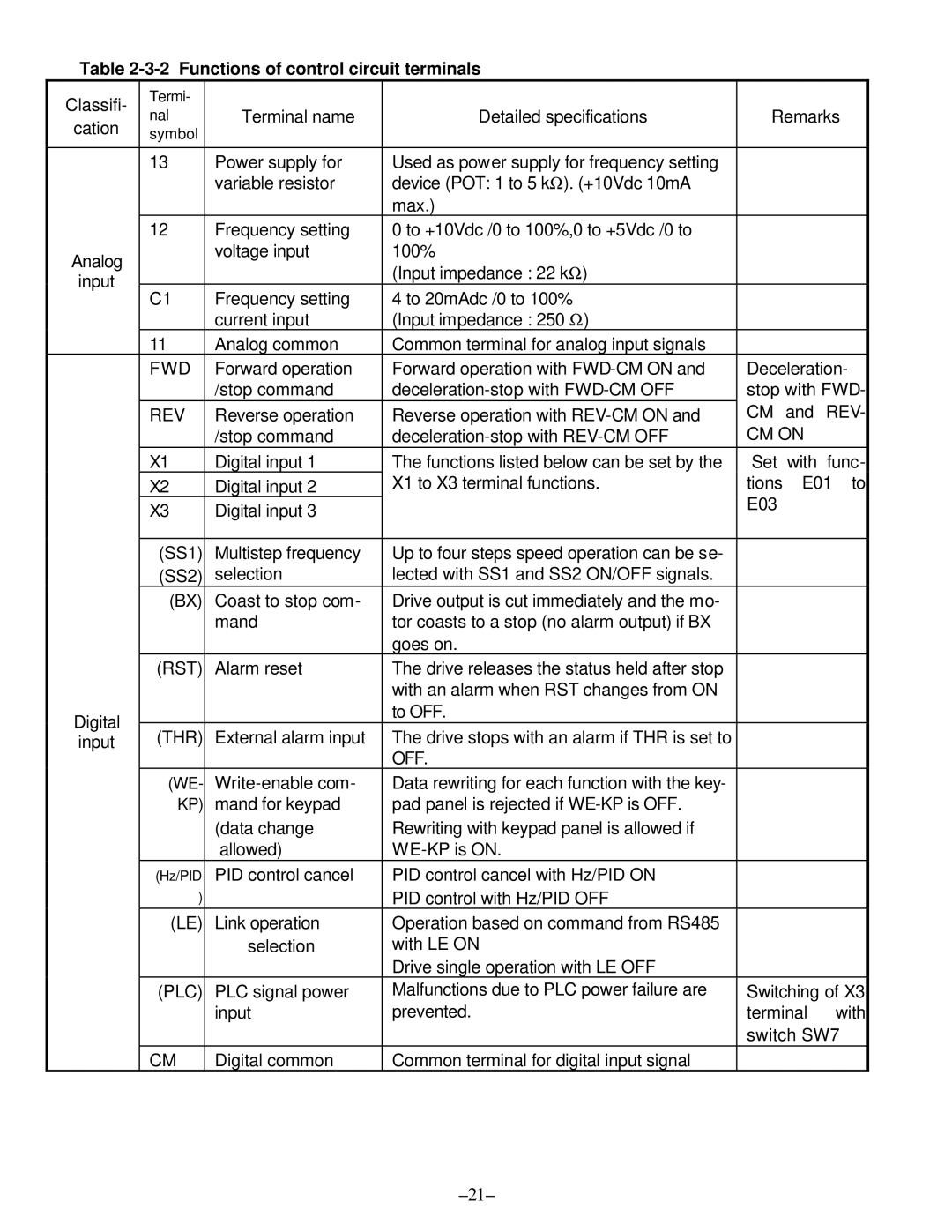
Table 2-3-2 Functions of control circuit terminals
Classifi- | Termi- |
|
|
|
|
| |
nal | Terminal name | Detailed specifications | Remarks | ||||
cation | |||||||
symbol |
|
|
|
|
| ||
|
|
|
|
|
|
| |
| 13 | Power supply for | Used as power supply for frequency setting |
|
|
| |
|
| variable resistor | device (POT: 1 to 5 kΩ). (+10Vdc 10mA |
|
|
| |
|
|
| max.) |
|
|
| |
| 12 | Frequency setting | 0 to +10Vdc /0 to 100%,0 to +5Vdc /0 to |
|
|
| |
Analog |
| voltage input | 100% |
|
|
| |
|
| (Input impedance : 22 kΩ) |
|
|
| ||
input |
|
|
|
|
| ||
C1 | Frequency setting | 4 to 20mAdc /0 to 100% |
|
|
| ||
|
|
|
| ||||
|
| current input | (Input impedance : 250 Ω) |
|
|
| |
| 11 | Analog common | Common terminal for analog input signals |
|
|
| |
| FWD | Forward operation | Forward operation with | Deceleration- | |||
|
| /stop command | stop with FWD- | ||||
| REV | Reverse operation | Reverse operation with | CM | and | REV- | |
|
| /stop command | CM ON |
| |||
| X1 | Digital input 1 | The functions listed below can be set by the | Set | with | func- | |
| X2 | Digital input 2 | X1 to X3 terminal functions. | tions | E01 to | ||
| X3 | Digital input 3 |
| E03 |
|
| |
|
|
|
|
| |||
|
|
|
|
|
|
| |
| (SS1) | Multistep frequency | Up to four steps speed operation can be se- |
|
|
| |
| (SS2) | selection | lected with SS1 and SS2 ON/OFF signals. |
|
|
| |
| (BX) | Coast to stop com- | Drive output is cut immediately and the mo- |
|
|
| |
|
| mand | tor coasts to a stop (no alarm output) if BX |
|
|
| |
|
|
| goes on. |
|
|
| |
| (RST) | Alarm reset | The drive releases the status held after stop |
|
|
| |
|
|
| with an alarm when RST changes from ON |
|
|
| |
Digital |
|
| to OFF. |
|
|
| |
(THR) | External alarm input | The drive stops with an alarm if THR is set to |
|
|
| ||
input |
|
|
| ||||
|
|
| OFF. |
|
|
| |
| (WE- | Data rewriting for each function with the key- |
|
|
| ||
| KP) | mand for keypad | pad panel is rejected if |
|
|
| |
|
| (data change | Rewriting with keypad panel is allowed if |
|
|
| |
|
| allowed) |
|
|
| ||
| (Hz/PID | PID control cancel | PID control cancel with Hz/PID ON |
|
|
| |
| ) |
| PID control with Hz/PID OFF |
|
|
| |
| (LE) | Link operation | Operation based on command from RS485 |
|
|
| |
|
| selection | with LE ON |
|
|
| |
|
|
| Drive single operation with LE OFF |
|
|
| |
| (PLC) | PLC signal power | Malfunctions due to PLC power failure are | Switching of X3 | |||
|
| input | prevented. | terminal | with | ||
|
|
|
| switch SW7 | |||
| CM | Digital common | Common terminal for digital input signal |
|
|
| |
