2-3-4 Connection examples
1) Keypad panel operation
E![]()
When
DC reactor is used | P1 | P(+) |
|
MCCB | Fuse | P1 |
| L1/R | |
230V input series |
| |
| L2/S | |
200 to 230V |
| |
50/60Hz |
| L3/T |
|
|
*2
P(+) P(+)
U |
|
V | M |
W | 3~ |
|
230V input series
200 to 240V
50/60Hz
![]()
![]()
![]() G
G![]() G
G ![]()
MCCB | Fuse |
|
|
| L1/L | PRG | RUN |
|
| RESET |
|
|
| FUNC | STOP |
| L2/N | DATA | |
|
|
|
Frequency setting POT (VR)
13 | +10Vdc |
|
| |
|
|
| ||
12 | 22kΩ | Pulse output FM | ||
11 | 0V | |||
|
| |||
| Ω | EXT |
| |
C1 | 250 |
|
| |
| +24 to +27Vdc |
| ||
|
|
| ||
|
| INT | 30A | |
|
|
| ||
4.7kΩ
FWD |
|
| 30B | |
REV |
|
| 30C | |
X1 |
|
|
| |
X2 |
| SW7 | ||
|
|
| ||
X3 | INT |
| PLC | |
X3 | EXT |
| X3 | |
CM PLC |
| |||
0V | 1 | 2 | ||
| ||||
Analog monitor
Alarm output for any fault
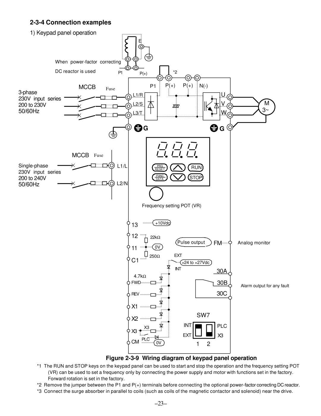
Figure 2-3-9 Wiring diagram of keypad panel operation
*1 The RUN and STOP keys on the keypad panel can be used to start and stop the operation and the frequency setting POT (VR) can be used to set a frequency only by connecting the power supply and motor with functions set in the factory. Forward rotation is set in the factory.
*2 Remove the jumper between the P1 and P(+) terminals before connecting the optional