Classifi- | Termi- |
|
|
| |
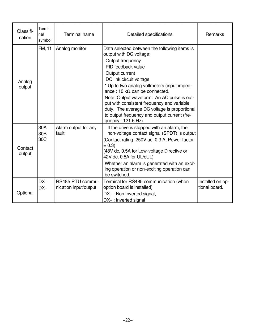
nal | Terminal name | Detailed specifications | Remarks | ||
cation | |||||
symbol |
|
|
| ||
|
|
|
| ||
|
|
|
|
| |
| FM, 11 | Analog monitor | Data selected between the following items is |
| |
|
|
| output with DC voltage: |
| |
|
|
| Output frequency |
| |
|
|
| PID feedback value |
| |
|
|
| Output current |
| |
Analog |
|
| DC link circuit voltage |
| |
|
| * Up to two analog voltmeters (input imped- |
| ||
output |
|
|
| ||
|
|
| ance : 10 kΩ can be connected. |
| |
|
|
| Note: Output waveform: An AC pulse is out- |
| |
|
|
| put with consistent frequency and variable |
| |
|
|
| duty. The average DC voltage is proportional |
| |
|
|
| to output frequency and output current (fre- |
| |
|
|
| quency : 121.6 Hz). |
| |
| 30A | Alarm output for any | If the drive is stopped with an alarm, the |
| |
| 30B | fault |
| ||
| 30C |
| (Contact rating: 250V ac, 0.3 A, Power factor |
| |
Contact |
|
| = 0.3) |
| |
|
| (48V dc, 0.5A for |
| ||
output |
|
|
| ||
|
| 42V dc, 0.5A for UL/cUL) |
| ||
|
|
|
| ||
|
|
| Whether an alarm is generated with an excit- |
| |
|
|
| ing operation or |
| |
|
|
| be switched. |
| |
| DX+ | RS485 RTU commu- | Terminal for RS485 communication (when | Installed on op- | |
| − | nication input/output | option board is installed) | tional board. | |
Optional | DX |
|
|
| |
|
| DX+ : |
| ||
|
|
| DX− : Inverted signal |
|
Page 24
Image 24