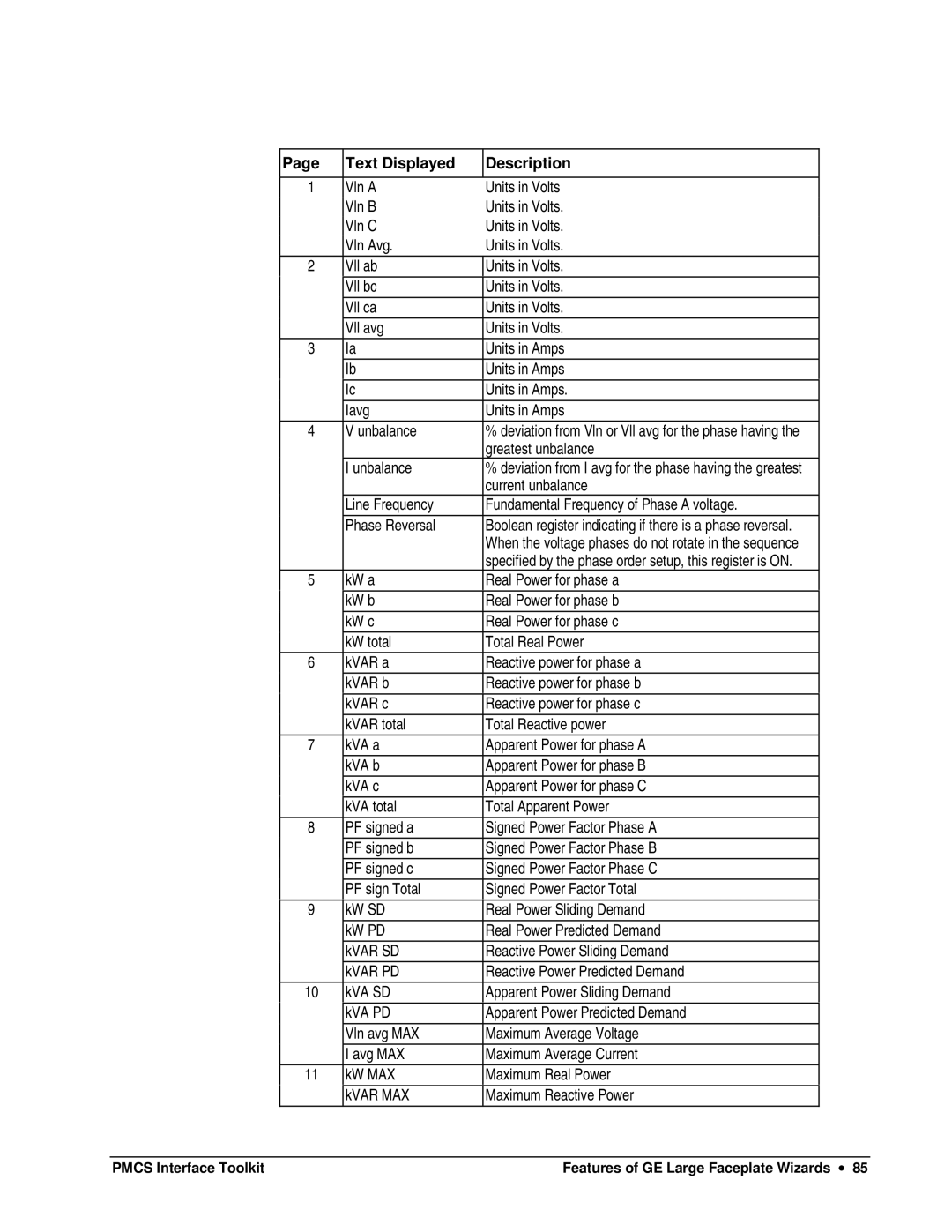
Page | Text Displayed | Description |
|
|
|
1 | Vln A | Units in Volts |
| Vln B | Units in Volts. |
| Vln C | Units in Volts. |
| Vln Avg. | Units in Volts. |
2 | Vll ab | Units in Volts. |
|
|
|
| Vll bc | Units in Volts. |
| Vll ca | Units in Volts. |
| Vll avg | Units in Volts. |
3 | Ia | Units in Amps |
| Ib | Units in Amps |
| Ic | Units in Amps. |
| Iavg | Units in Amps |
4 | V unbalance | % deviation from Vln or Vll avg for the phase having the |
|
| greatest unbalance |
| I unbalance | % deviation from I avg for the phase having the greatest |
|
| current unbalance |
| Line Frequency | Fundamental Frequency of Phase A voltage. |
| Phase Reversal | Boolean register indicating if there is a phase reversal. |
|
| When the voltage phases do not rotate in the sequence |
|
| specified by the phase order setup, this register is ON. |
5 | kW a | Real Power for phase a |
|
|
|
| kW b | Real Power for phase b |
| kW c | Real Power for phase c |
| kW total | Total Real Power |
6 | kVAR a | Reactive power for phase a |
| kVAR b | Reactive power for phase b |
| kVAR c | Reactive power for phase c |
| kVAR total | Total Reactive power |
7 | kVA a | Apparent Power for phase A |
| kVA b | Apparent Power for phase B |
| kVA c | Apparent Power for phase C |
| kVA total | Total Apparent Power |
8 | PF signed a | Signed Power Factor Phase A |
| PF signed b | Signed Power Factor Phase B |
| PF signed c | Signed Power Factor Phase C |
| PF sign Total | Signed Power Factor Total |
|
|
|
9 | kW SD | Real Power Sliding Demand |
| kW PD | Real Power Predicted Demand |
| kVAR SD | Reactive Power Sliding Demand |
| kVAR PD | Reactive Power Predicted Demand |
10 | kVA SD | Apparent Power Sliding Demand |
| kVA PD | Apparent Power Predicted Demand |
| Vln avg MAX | Maximum Average Voltage |
| I avg MAX | Maximum Average Current |
11 | kW MAX | Maximum Real Power |
|
|
|
| kVAR MAX | Maximum Reactive Power |
PMCS Interface Toolkit | Features of GE Large Faceplate Wizards ∙ 85 |
