Part Number 0700022F
DisplayMaker Legacy 72S, 72SR
Legal notices
Iii
Revision Log
Revision Description
DOC Canada
Regulatory Statements
Telecommunications Network Statement
About This Manual
Ink and Media, shows you how to install ink and media
Vii
Conventions
Hinweis
Vorsicht
Viii
Table of Contents
Ink and Media
Using the Control Panel
Report Individual Bad Jets Clear Individual Bad Jets
Calibrating the Printer
Maintaining the Printer
Xii
Print Server Setup
Printer Driver Setup
Configuring and Controlling the Printer
Index
Technical Specifications
Troubleshooting
Xiv
Getting Started
Getting Started
Electrical Environmental
Operating Requirements
Operating Requirements
Important Operating Notes
Operating Requirements
Safety Warnings
Operating Requirements
Examine the shipping packaging for shipping damage
Unpacking Assembly
Unpacking and Assembly
Required Tools Unpacking
Lift the box straight up and off of the pallet
Stand assembly
Through the legs
If purchased, install the VOC plenum kit
Angle exaggerated for clarity
Will use them later to pull the ink drain tubes
Unpacking and Assembly
Unpacking and Assembly
Unpacking and Assembly
Unpacking and Assembly
Remove the pump cover see Fig
Install the reservoir wire rack see Fig
Installing the reservoirs
Install the five reservoirs
Connecting the drain tube to the reservoir
Final Assembly 30. Install the vacuum reservoir see Fig
Sensor cable Drain tube
Supply & takeup cable
From sensor From V/P system
Do not turn the nut on the turnbuckle. Turning
Unpacking and Assembly
15. Auxiliary vacuum power
Connecting to the Print Server
Unpack the Printheads
First-Time Power-Up and Test Print
First-Time Power-Up and Test Print
18. Service station wiper bar
First-Time Power-Up and Test Print
19. Ink color locations
Solvent Y M C K
Load Media
Install and set up the RIP
First-Time Power-Up and Test Print
Print server RIPs the job
Workflow Overview
Daily Startup Printing
Workflow Overview
Server sends the image to the printer for printing
11a 11b
Parts Overview
Parts Overview
Index Description
VideoNet port connects printer to print server
Index Description
Printheads Ink System
Special Features
Calibration Media Handling
Special Features
Special Features
Overview Front Navigation Keys Menu Menu Tree
Using the Control Panel
Ready Status Screen Front Menu
Overview
Ready Screen Front Menu
Overview
Tip
Front
Front
Media Info, Ink Info screens
Front
Front
Key Description
Navigation Keys
Menu
Menu
Calibrate Printer
Configure for Profile Creation cut sheet printing only
Weight media such as paper or fabrics
Heater Temp Settings selects one of several pre-defined
Temperatures, plus one custom, user-defined setting. Exces
Dried prints. For instructions, see Setting Heater Tempera
Margin Settings
Menu
Maintenance
Menu
Service Printer User Diagnostics
Menu Tree
Menu Tree
Calibrate Printer
Maintenance
Service Printer User Diagnostics
Ink and Media
Ink and Media
Condition Meaning
Ink System Overview
Idle Jet Maintenance
Print mode menu appears, with three options
General Printing Tips
General Printing Tips
Checking Jet Health
Checking jet health and recovering jets
Checking Jet Health
Print Prime Bars Purge-n-Wipe Printheads
Jets in other colors. Repeated single-color purges
Print Jet-Out Lines
Pressure is applied to each printhead, but a possible
Side effect of repeated single-color purges is clogged
Refilling Ink
Refilling Ink
Refilling Ink
Capping the Printheads
Press the Sleep key on the Front Page screen
Press the Proceed key to cap the printheads
Capping station pad, wear latex gloves to prevent
Staining your hands during this procedure
Press Proceed
Since some ink may spill from the plastic-wrapped
Purge the printheads
Press the ! Proceed key
Print the prime bars
Supply only
Loading Roll-Fed Media
Loading Roll-Fed Media
Media path from supply to takeup
Media edges to a reference mark on the platen
Printer automatically locates the right and left
Media settings
Press the ! key to continue
You are now ready to begin printing
Tip
Unloading and Cutting Roll-Fed Media
Unloading Cutting Roll-Fed Media
Takeup spool pin release tool
Respooling Media
Respooling Media
Respool Media
Press the ! Proceed key to respool the media
Loading Rigid Media
Loading Rigid Media
Load a sheet of media onto the printer
Loading and Aligning the Sheet
Printer moves the media to the proper position for printing
Front Page screen of the control panel
Before a print job is received, you can unload
Edge-to-Edge Printing
Unloading and Reloading Rigid Media
Unloading and Reloading Rigid Media
Media Wizard
Media Wizard
Feed method Roll or Cut Sheet
Media Wizard
Setting Heater Temperatures
Press the , or keys repeatedly to select a setting
Press ! to select a setting, or � to cancel
Setting Heater Temperatures
Calibrating the Printer
Calibrating the Printer
Or Manual Jet Mapping
When to Calibrate
AutoJet
AutoJet
Printer prints an AutoJet report
AutoTune
AutoTune
AutoRecover
Auto Calibrations
Auto Calibrations
Choose whether to perform a Purge-n-Wipe
Manual Calibrations
Manual Calibrations
Long edge of a letter-size or A4 sheet of paper
Then measure the transferred marks and adjust
To avoid cutting the 10-inch pattern from the media
Web, copy the marks from the 10-inch calibration to
Press the ! key
Manual X Head Registration
Repeat steps 4 through 6 for each of the heads
4-7 for details
AutoBiDi Calibration is the automatic version of this
Calibration. Try AutoBiDi first before running this
Manual calibration see Auto Calibrations on
Repeat steps 6 through 8 for each of the twelve heads
Printheads as necessary to ensure the maximum
AutoJet is the automatic version of this calibration
See AutoJet on page 4-3 for details
For best results, print the prime bars and purge
Printer prints a jet map test pattern
Press , and to select a head number, then press ! Proceed
Report Individual Bad Jets
Clear Individual Bad Jets
Clear All Bad Jets
View Current Bad Jets
Press
Jet Status Lines Default Registration Data
AutoSet Summary
Straightening the Media Path
Straightening the Media Path
Linearization
Maintaining the Printer
Maintaining the Printer
Interval At control panel warning
Task Description Interval Weekly or as needed
Interval As needed
Clean the Rail and Bearings
Clean the Rail and Bearings
Clean the Rail and Bearings
Clean the left and right inside bearings
Cleaning the Encoder Strip
Close the stopcock valve on the drain tube
Empty Excess Ink
Procedures
Printhead Maintenance
Do not USE Isopropyl Alcohol on the Printheads
Cleaning Clogged Ink Jets
Cleaning Clogged Ink Jets
Solvent-soaked Cleaning pad
Cleaning the doctor blade
Set the Printhead and Camera Height
Set the Printhead and Camera Height
Printer Settings
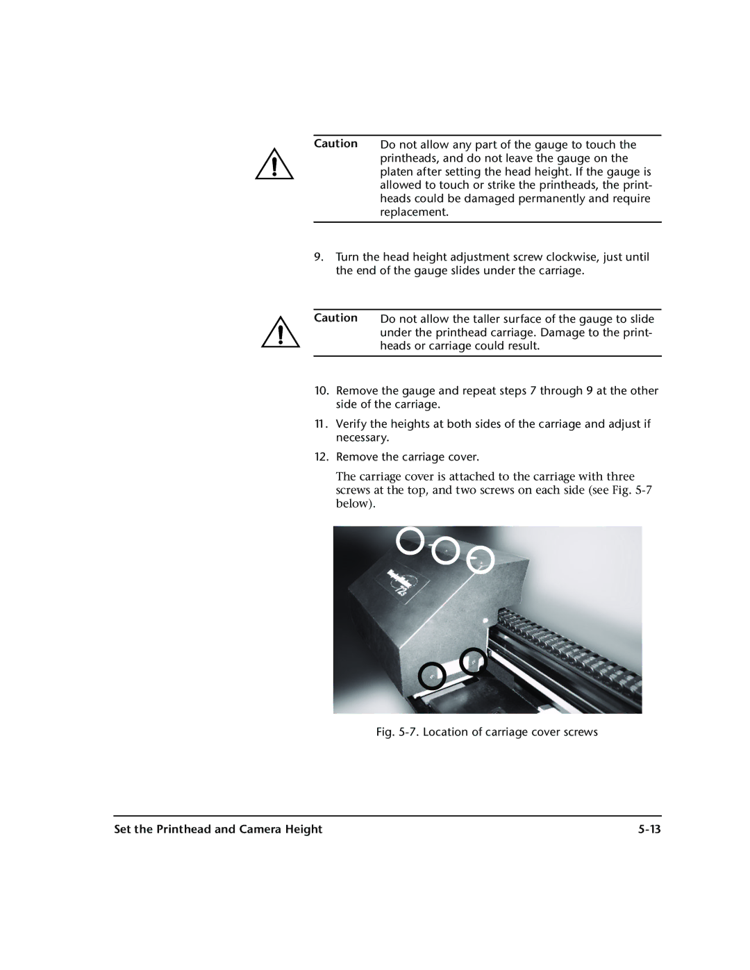
Location of carriage cover screws
Camera enclosure mounting screws Set the camera height
Press to calibrate the service station, or to continue
Set the Printhead and Camera Height
Calibrate the Service Station
Pin plate Wiper Printhead
Calibrate the Service Station
Disconnect the level sensor cable from the reservoir
Replace Ink Filters
Replace Ink Filters
Use a Phillips screwdriver to loosen the filter clamp
Tighten the filter clamp
Reconnect the level sensor cable
Filters
Shipping
Extended Power Down and Restart
Power Down Restart
Extended Power Down and Restart
Press the � Menu In key Load media
Recover missing jets
Heads
Print Server Setup
Print Server Setup
Printer icon menu
Status Configure Control
Printer Status dialog box
Configuring and Controlling the Printer
Approximate Ink Remaining
Printer Status
Software
ColorMark CMS
Printer Name
Set or verify the printer configuration
Lighter Prints-Darker Prints
Dithering
Ink Level
Selecting Server Options
Configuring the Input Port
Tiling
Input Port Options
Port Name
RIP Options
EPS/TIFF Options
Length
Printing Options
Step-and-Repeat settings
Click OK to save the settings
Drag the job to an Output queue
Open the Input Attention Queue
Send an EPS or bitmap file to the print server
Selecting Server Options
Selecting Server Options
Click the Options tab to specify options
Options tab
ColorMatch RGB SRGB ColorMark RGB ColorMark 2 RGB
Color Management
ColorSpan Workflow ColorMark CMS
Adobe RGB Apple RGB
Color Management
Color Profile
Trumatch matches Trumatch spot colors and full-color images
Color Management
10. Port configuration for ICC workflow
Color Calibration
Click the button marked Print Calibration
Select a profile to calibrate Click the OK button
Click the button marked Take Calibration Readings
Accept Yes or cancel No the calibration data
Accept or cancel the calibration data
Color Calibration
Printer Driver Setup
Printer Driver Setup
Details
Printer Features
Printer Driver Setup
Selecting an Output Color Space
Print or download the document
Select Printer Features
Printer Features
Click Print
Sample color space setting QuarkXPress shown
Print or download the document
Printer Driver Setup
Technical Specifications
Technical Specifications
General
Specifications
Required electrical circuit
Specifications
Operating
Performance
SolaChrome-HR head cleaning solvent solution
MacDermid ColorSpan Supplies Sales
Supplies and Accessories
Troubleshooting
Troubleshooting
Does the printer’s power come ON?
Troubleshooting Checklist
Page
Troubleshooting Checklist
Warranty Claims
Warranty Claims
Causes that are covered by the manufacturer’s warranty
Diagnostics
Diagnostics
Code, Message Cause What to Do
Table B-1. Actions and Warnings
Printer. If it will not cool, unplug
IS-90 91 92 93 94 color Pump
LS Image Sensor
PR Pinch Rollers
VN VideoNet
Page
Index-1
Index
Index-2
AutoJet 2-6,4-3,4-7
Index-3
Index-4
Index-5
3-3,3-9
SolaChrome-HR Solvent Ink 1-3,1-24,3-2
3-9
Index-6