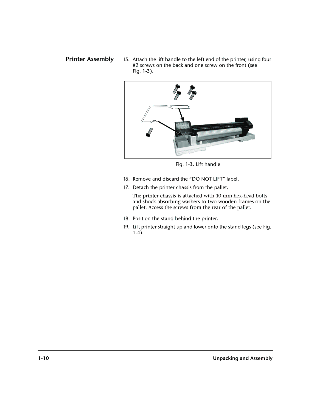
Printer Assembly 15. Attach the lift handle to the left end of the printer, using four #2 screws on the back and one screw on the front (see
Fig.
Fig. 1-3. Lift handle
16.Remove and discard the “DO NOT LIFT” label.
17.Detach the printer chassis from the pallet.
The printer chassis is attached with 10 mm
18.Position the stand behind the printer.
19.Lift printer straight up and lower onto the stand legs (see Fig.
Unpacking and Assembly |
