User Service Guide
Legal Notices
Table of Contents
System Specifications
113
149
145
197
173
183
Backplane Rear View Cell Board
List of Figures
Power Status Window
List of Tables
List of Examples
Page
Intended Audience
About This Document
Document Organization
Typographic Conventions
Publishing History
Related Information
HP Encourages Your Comments
Page
Overview
Server History and Specifications
Server Components
Superdome Cabinet Components
Power Subsystem
DC Power
AC Power
Enabling 48 Volts
Power Sequencing
Cooling System
Platform Management
Utilities Subsystem
PM3 Functionality
CLU Functionality
Management Processor
System Clocks
Management Processor
Compact Flash
Crossbar Chip
Backplane
Backplane Monitor and Control
Switch Fabrics
I2C Bus Distribution
Clock Subsystem
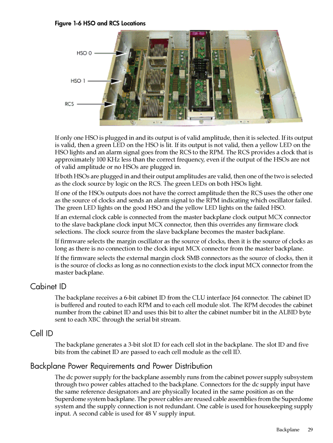
Sx2000 RCS Module
HSO LED Status Indicator Meaning
Hot-Swap Oscillator
Cell ID
Backplane Power Requirements and Power Distribution
Cabinet ID
CPUs and Memories
Backplane Power Supply Module
Processor Interface
Cell Controller
Cell Memory System
Processors
Rules for Processor Mixing
Supported Processors and Minimum Firmware Versions
Memory Interconnect
Memory Controller
Dimm Architecture
Memory Bank Attribute Table
Mixing Different Sized DIMMs
Memory Interleaving
Link Interleaving
Memory Error Protection
Cell Map
Dram Erasure
PDC Functional Changes
Platform Dependent Hardware
Cell OL
Reset
Subsystem
SBA Chip CC-to-Ropes
PCI-X Backplane Functionality
11 PCI-X I/O Rope Mapping
Ropes-to-PCI LBA Chip
Mixed PCI-X and PCI Express I/O Chassis
PCI Slots
12 PCIe I/O Rope Mapping PCI Hot-Swap Support
System Management Station
User Accounts
New Server Cabling
Link Cable
SMS Lifecycles
13 e-Link Cable
Itanium Firmware for HP Integrity Superdome/sx2000
Firmware
Clock Cable
User Interface
Error and Event IDs
Itanium System Firmware Functions
PA-RISC Firmware for HP 9000/sx2000 Servers
PA-RISC System Firmware Functions
Server Configurations
Basic Configuration Rules
Server Errors
Dimensions and Weights
System Specifications
Component Dimensions
Component Weights
Shipping Dimensions and Weights
Electrical Specifications
IOX Cabinet Weights
Miscellaneous Dimensions and Weights
Available Power Options
Power Options
Grounding
Circuit Breaker
Power Requirements Without SMS
System Power Requirements
IOX Cabinet Power Cords
Component Power Requirements
IOX Cabinet Power Requirements
Environmental Requirements
Temperature and Humidity Specifications
Power Dissipation
Cells Memory DIMMs Fully Typical Power Cooling BTU/Hr
Airflow
Acoustic Noise Specification
17 Physical Environmental Specifications
Airflow Diagram
Page
Introduction
Installing the System
Communications Interference
Electrostatic Discharge
Public Telecommunications Network Connection
Unpacking and Inspecting the System
Verifying Site Preparation
Checking the Inventory
Inspecting the Shipping Containers for Damage
Normal Tilt Indicator
Unpacking and Inspecting Hardware Components
Inspection Precautions
Claims Procedures
Unpacking the Cabinet
Tools Required
Front of Cabinet Container
Removing the Ramps from the Pallet
I/O Chassis Mounting Screws
Power Supply Mounting Screws Location
Unpacking and Inspecting the System
Shipping Strap Location
Moving the Cabinet Off the Pallet
Removing the Mounting Brackets
Carefully roll the cabinet down the ramp Figure
Returning Equipment
Power Cord Option 6 and 7 Details
Unpacking the Pdca
Unpacking and Installing the Blower Housings and Blowers
Setting Up the System
13 Removing Protective Cardboard from the Housing
15 Installing the Front Blower Housing
Attaching the Side Skins
Attaching the Side Skins and Blower Side Bezels
17 Attaching the Rear Side Skin
18 Attaching the Front Side Skins
Attaching the Blower Side Bezels
Place the side bezel slightly above the blower housing frame
Attaching the Leveling Feet and Leveling the Cabinet
Installing the Front Door Bezels
21 Installing the Lower Front Door Assembly
22 Installing the Upper Front Door Assembly
Installing the Rear Blower Bezel
23 Installing the Rear Blower Bezel
Installing the Front Blower Bezel
24 Installing the Front Blower Bezel
Wiring Check
Installing and Verifying the Pdca
25 Pdca Assembly for Options 6
27 a 5-Wire Connector
Wire
30 Wall Receptacle Pinouts
Checking Voltage
Removing the EMI Panels
31 Power Supply Indicator LED
32 Removing Front EMI Panel Screw
Routing the I/O Cables
Connecting the Cables
35 Routing I/O Cables
Installing the SMS Support Shelf
Installing the Support Management Station
SMS Software Utilities
Connecting the SMS to the Superdome
SMS Software and Superdome Firmware Downloading Procedure
Superdome Firmware Instructions
Configuring the Event Information Tools
Example 3-1 Directory Example sx2000\8.7f
Example 3-2 Directory Example sx2000/8.7f
EIT Tools Functionality
Turning On Housekeeping Power
Where to Find the EIT Documentation
36 Front Panel with HKP and Present LEDs
Connecting the MP to the Network
Connecting the MP to the Customer LAN
38 MP LAN Connection Location
Setting the Customer IP Address
39 LAN Configuration Screen
Connecting to the MP
Booting and Verifying the System
Telnet MP hostname
43 MP Command Option
Booting the HP Integrity Superdome/sx2000 to an EFI Shell
Powering On the System 48 V Power Supply
47 HP Integrity Superdome/sx2000 EFI Boot Manager
Verifying the System
Booting an HP 9000 sx2000 Server to BCH
Cabinet. Observe Power Switch on and Power enabled Figure
Running Just
Running JET Software
Attaching the Rear Kick Plates
Offline Diagnostic Environment
Power Cycling After Using JET
53 Attaching Rear Kick Plates
Reinstall the front EMI panel Figure
56 Reinstalling the Back EMI Panel
Conducting a Post-Installation Check
Operating Systems Supported on Cell-based HP Servers
Booting and Shutting Down the Operating System
HP Integrity Boot Configuration Options
System Boot Configuration Options
HP 9000 Boot Configuration Options
System Boot Configuration Options
Booting and Shutting Down the Operating System
NPars Boot Mode
HP-UX Support for Cell Local Memory
Booting and Shutting Down HP-UX
Adding HP-UX to the Boot Options List
Procedure 4-1 Adding an HP-UX Boot Option
Booting HP-UX
Procedure 4-2 HP-UX Booting BCH Menu
Standard HP-UX Booting
Procedure 4-3 HP-UX Booting EFI Boot Manager
Boot bootvariable
Procedure 4-4 HP-UX Booting EFI Shell
Procedure 4-5 Single-User Mode HP-UX Booting BCH Menu
Single-User Mode HP-UX Booting
Example 4-1 Single-User HP-UX Boot
ISL hpux -is boot /stand/vmunix
HP-UX
Procedure 4-6 Single-User Mode HP-UX Booting EFI Shell
Procedure 4-8 LVM-Maintenance Mode HP-UX Booting EFI Shell
LVM-Maintenance Mode HP-UX Booting
Procedure 4-7 LVM-Maintenance Mode HP-UX Booting BCH Menu
Shutting Down HP-UX
Procedure 4-9 Shutting Down HP-UX
Booting and Shutting Down HP OpenVMS
HP OpenVMS I64 Support for Cell Local Memory
Adding HP OpenVMS to the Boot Options List
Procedure 4-10 Adding an HP OpenVMS Boot Option
Booting and Shutting Down the Operating System
Procedure 4-12 Booting HP OpenVMS EFI Shell
Booting HP OpenVMS
Procedure 4-11 Booting HP OpenVMS EFI Boot Manager
Shutting Down HP OpenVMS
Procedure 4-13 Shutting Down HP OpenVMS
Microsoft Windows Support for Cell Local Memory
Booting and Shutting Down Microsoft Windows
Procedure 4-14 Adding a Microsoft Windows Boot Option
Adding Microsoft Windows to the Boot Options List
Fs0\ msutil\nvrboot
Booting Microsoft Windows
Procedure 4-15 Windows Booting
Shutting Down Microsoft Windows
Procedure 4-16 Windows Shutdown from the Command Line
Linux Support for Cell Local Memory
Booting and Shutting Down Linux
Procedure 4-17 Adding a Linux Boot Option
Adding Linux to the Boot Options List
Procedure 4-18 Booting Red Hat Enterprise Linux EFI Shell
Booting Red Hat Enterprise Linux
Booting SuSE Linux Enterprise Server
\efi\SuSE\elilo.efi \efi\SuSE\elilo.conf
Shutting Down Linux
Procedure 4-20 Shutting Down Linux
144
Table A-1 Front Panel LEDs
Sx2000 LEDs
MOP
Table A-2 Power and OL* LEDs
Figure A-1 Utilities Table A-3 OL* LED States
SMG
Table A-4 PDH Status and Power Good LED States
CA Command
Management Processor Commands
BO Command
CC Complex Configuration
CC Command
Example B-2 CA Command
CP Cells Assigned by Partition
CP Command
Example B-3 CC Command
DC Command
Date Command
DF Display Fruid
DF Command
Example B-6 DC Command
DI Disconnect Remote or LAN Console
DI Command
Example B-7 DF Command
EL Command
DL Command
HE Help Menu
HE Command
Example B-10 EL Command
ID Configure Complex Identification
ID Command
Example B-11 HE Command
IO Display Connectivity Between Cells and I/O
IO Command
Example B-12 ID Command
LC Command
IT Command
MA Command
LS Command
PD Command
ND Command
PE Power Entity
PE Command
Example B-19 PD Command
PS Power and Configuration Status
PS Command
Example B-20 PE Command for a Compute Cabinet
RE Reset Entity
RE Command
Example B-21 PS Command
RL Re-key Complex Profile Lock
RL Command
RS Command
RR Command
SO Command
SA Command
Sysrev Display System and Manageability Firmware Revisions
Sysrev Command
Example B-26 SO Command
TE Command
TC Command
WHO Command
VM Command
XD Diagnostic and Reset of MP
XD Command
Example B-31 WHO Command
Example B-32 XD Command
Shutting Down the System
Powering the System On and Off
Checking System Configuration
Figure C-3 Checking for Other Users
Figure C-6 Example of Partition State
Shutting Down the Operating System
Preparing the Partitions for Shutdown
Figure C-8 Entering the rr Command
Figure C-9 Using the de -sCommand
Powering Off the System
Cabinet is now powered off
Turning On Housekeeping Power
Figure C-14 BPS LEDs
Powering On the System Using the PE Command
Figure C-15 Power Entity Command
Figure C-17 Power Status Window
Templates
Templates
Figure D-2 SD16 and SD32 Space Requirements
Computer Room Layout Plan
Equipment Footprint Templates
Figure D-4 Computer Floor Template
Figure D-5 Computer Floor Template
Figure D-6 Computer Floor Template
Figure D-7 Computer Floor Template
Figure D-8 Computer Floor Template
Figure D-9 SD32, SD64, and IOX Cabinet Templates
Figure D-10 SD32, SD64, and IOX Cabinet Templates
Figure D-11 SD32, SD64, and IOX Cabinet Templates
Figure D-12 SD32, SD64, and IOX Cabinet Templates
Figure D-13 SD32, SD64, and IOX Cabinet Templates
Figure D-14 SD32, SD64, and IOX Cabinet Templates
CLU
Index
Just
RCS
XBC