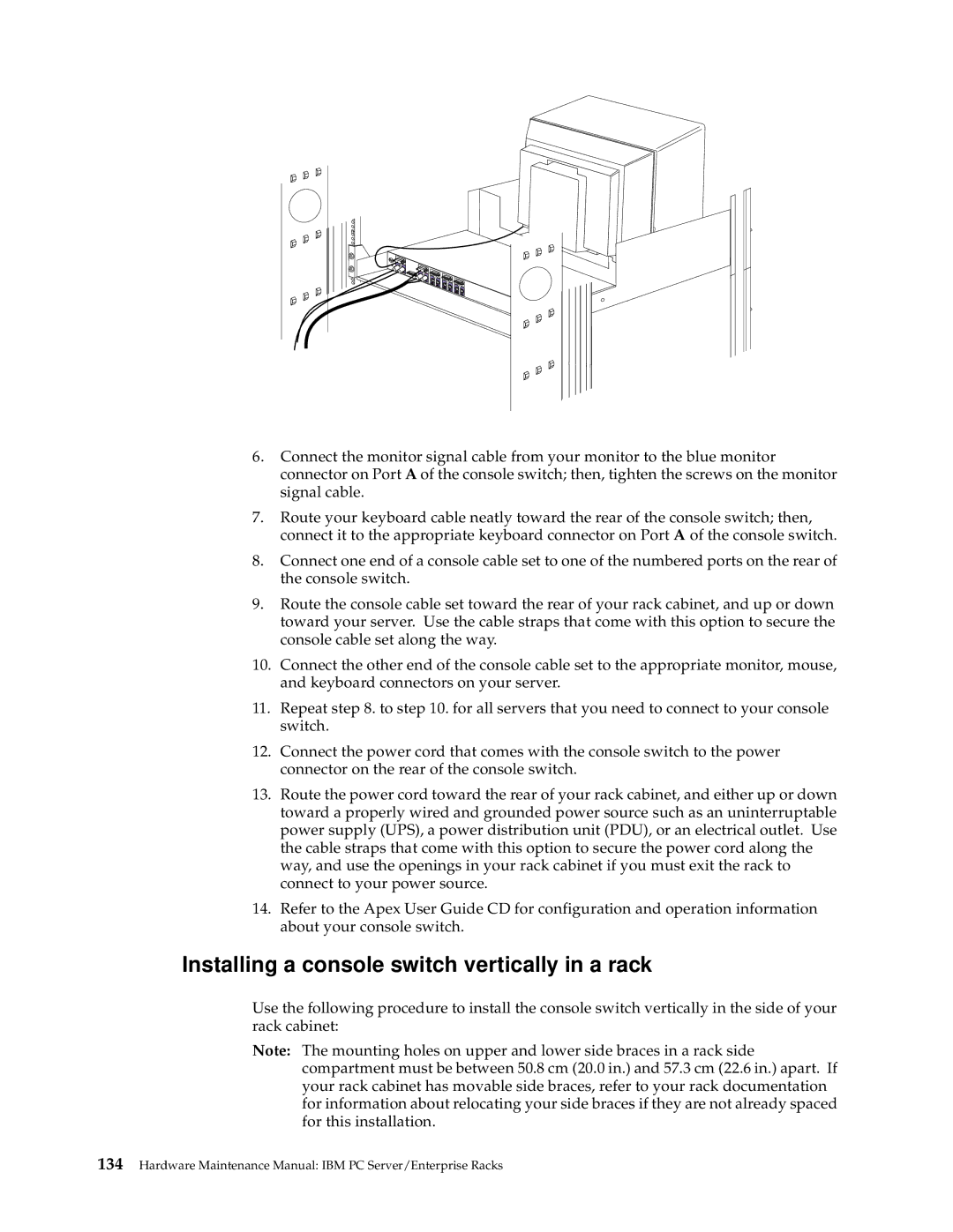
6.Connect the monitor signal cable from your monitor to the blue monitor connector on Port A of the console switch; then, tighten the screws on the monitor signal cable.
7.Route your keyboard cable neatly toward the rear of the console switch; then, connect it to the appropriate keyboard connector on Port A of the console switch.
8.Connect one end of a console cable set to one of the numbered ports on the rear of the console switch.
9.Route the console cable set toward the rear of your rack cabinet, and up or down toward your server. Use the cable straps that come with this option to secure the console cable set along the way.
10.Connect the other end of the console cable set to the appropriate monitor, mouse, and keyboard connectors on your server.
11.Repeat step 8. to step 10. for all servers that you need to connect to your console switch.
12.Connect the power cord that comes with the console switch to the power connector on the rear of the console switch.
13.Route the power cord toward the rear of your rack cabinet, and either up or down toward a properly wired and grounded power source such as an uninterruptable power supply (UPS), a power distribution unit (PDU), or an electrical outlet. Use the cable straps that come with this option to secure the power cord along the way, and use the openings in your rack cabinet if you must exit the rack to connect to your power source.
14.Refer to the Apex User Guide CD for configuration and operation information about your console switch.
Installing a console switch vertically in a rack
Use the following procedure to install the console switch vertically in the side of your rack cabinet:
Note: The mounting holes on upper and lower side braces in a rack side compartment must be between 50.8 cm (20.0 in.) and 57.3 cm (22.6 in.) apart. If your rack cabinet has movable side braces, refer to your rack documentation for information about relocating your side braces if they are not already spaced for this installation.