Design or topology remarks
Although this topology is very robust and offers high redundancy, newer topologies do exist. The drawback of this topology is the convergence time after a
It is good that in this topology we do not have to rely on trunk failover, which will not be supported on LACP trunks until the next (1.1) software release. This topology also does not need BladeServer NIC Teaming, although the BASP Teaming function should be considered with regards to its high availability capabilities.
As seen in 7.6, “Basic Layer 2 entry topology” on page 69, a better convergence time is reached with our basic topology but only by interacting with trunk failover and active or standby NIC teaming. Other ways to reduce the time that is required to recover from a topology change include recent enhancements to the Spanning Tree Protocol, such as Rapid Spanning Tree (IEEE 801.1w) , which is discussed in the next section or, alternatively, a Layer
Full configuration snapshots
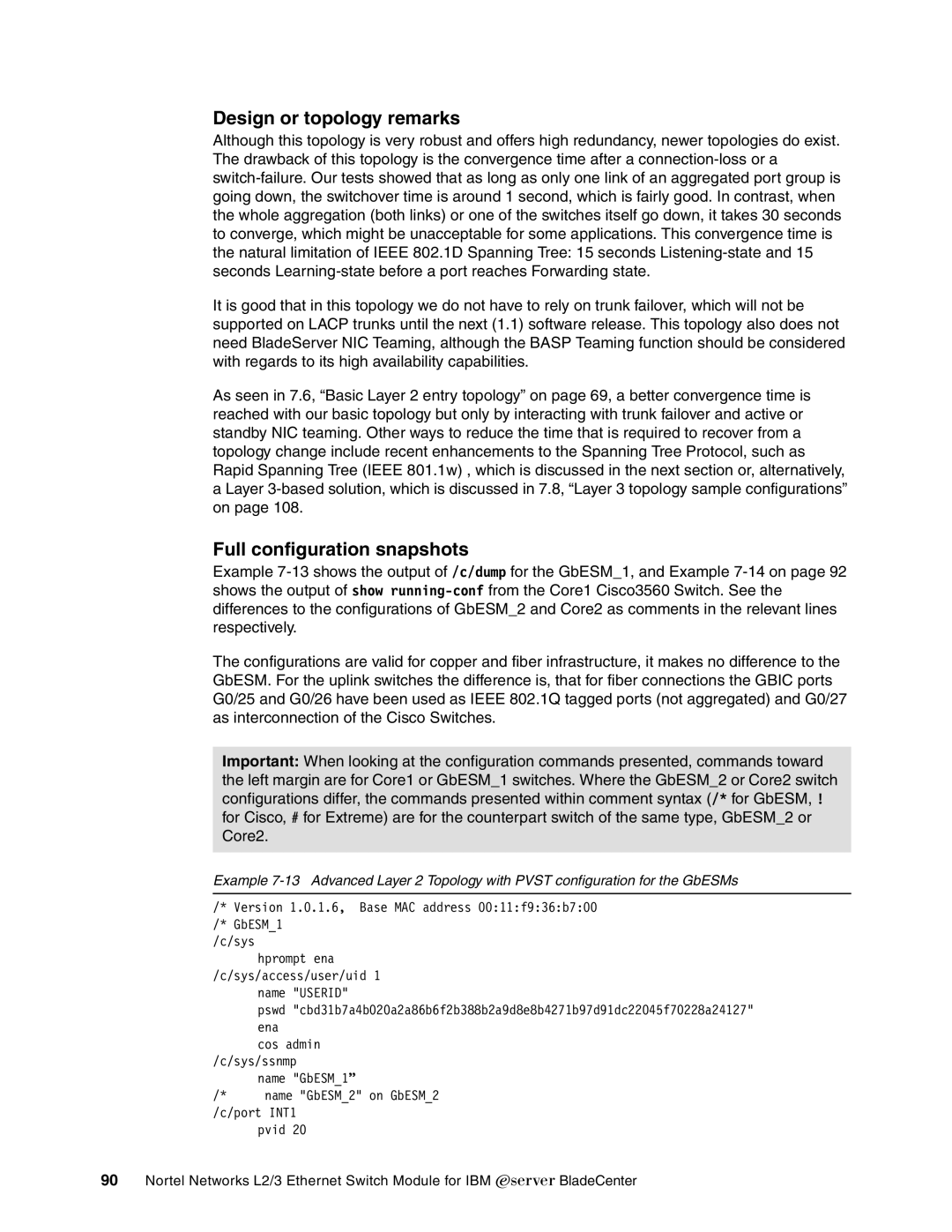
Example
The configurations are valid for copper and fiber infrastructure, it makes no difference to the GbESM. For the uplink switches the difference is, that for fiber connections the GBIC ports G0/25 and G0/26 have been used as IEEE 802.1Q tagged ports (not aggregated) and G0/27 as interconnection of the Cisco Switches.
Important: When looking at the configuration commands presented, commands toward the left margin are for Core1 or GbESM_1 switches. Where the GbESM_2 or Core2 switch configurations differ, the commands presented within comment syntax (/* for GbESM, ! for Cisco, # for Extreme) are for the counterpart switch of the same type, GbESM_2 or Core2.
Example
/* Version 1.0.1.6, Base MAC address 00:11:f9:36:b7:00 /* GbESM_1
/c/sys
hprompt ena
/c/sys/access/user/uid 1 name "USERID"
pswd "cbd31b7a4b020a2a86b6f2b388b2a9d8e8b4271b97d91dc22045f70228a24127" ena
| cos admin |
/c/sys/ssnmp | |
| name "GbESM_1” |
/* | name "GbESM_2" on GbESM_2 |
/c/port INT1 pvid 20
90Nortel Networks L2/3 Ethernet Switch Module for IBM Eserver BladeCenter