Configuration of Hot-standby for VRRP
The commands in Example
VRRP tracking allows a device to dynamically adjust its priority based on the availability of other resources, and allow a standby switch to become master if the current master loses access to those resources. Interface tracking counts the number of active IP interfaces and increments the VRRP priority 2 units for each by default. The effect of use of interface tracking in the sample configuration is to trigger VRRP failover and NIC teaming failover if
one of the uplink trunks connecting the master GbESM to the Core switches fails. Tracking with
Note: The VRRP tracking features of the GbESM are very flexible and allow granular control of when failover is triggered. There are many other possibilities besides what is shown in this sample. Planning and testing of these features is essential.
Note that a VLAN is created solely for the connection between the two switches. This is to avoid triggering the
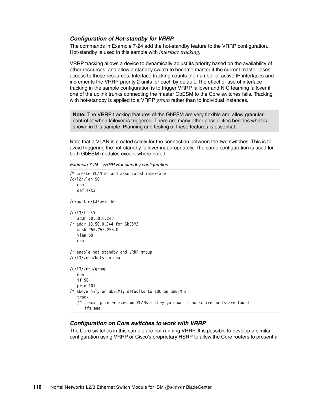
Example 7-24 VRRP Hot-standby configuration
/* create VLAN 50 and associated interface /c/l2/vlan 50
ena
def ext3
/c/port ext3/pvid 50
/c/l3/if 50
addr 10.50.0.243
/* addr 10.50.0.244 for GbESM2 mask 255.255.255.0
vlan 50 ena
/* enable hot standby and VRRP group /c/l3/vrrp/hotstan ena
/c/l3/vrrp/group ena
if 50 prio 101
/* above only on GbESM1; defaults to 100 on GbESM 2 track
/* track ip interfaces on VLANs - they go down if no active ports are found ifs ena
Configuration on Core switches to work with VRRP
The Core switches in this sample are not running VRRP. It is possible to develop a similar configuration using VRRP or Cisco’s proprietary HSRP to allow the Core routers to present a
116Nortel Networks L2/3 Ethernet Switch Module for IBM Eserver BladeCenter