|
|
|
|
|
| Uplinks | |
1 2 3 4 5 6 |
|
|
|
| 1 2 3 4 5 6 |
| |
GbESM1 |
|
|
|
| GbESM2 |
| |
M |
|
|
|
| M | Management | |
M |
|
|
|
| M | ||
|
|
|
| Module | |||
1 |
|
|
|
| 2 | ||
|
|
|
|
| 2 |
| |
1 | 2 | 1 | 2 | 1 | 2 | Blade | |
Blade | Blade | Blade | |||||
Servers | |||||||
Server1 | Server2 | Server14 | |||||
| |||||||
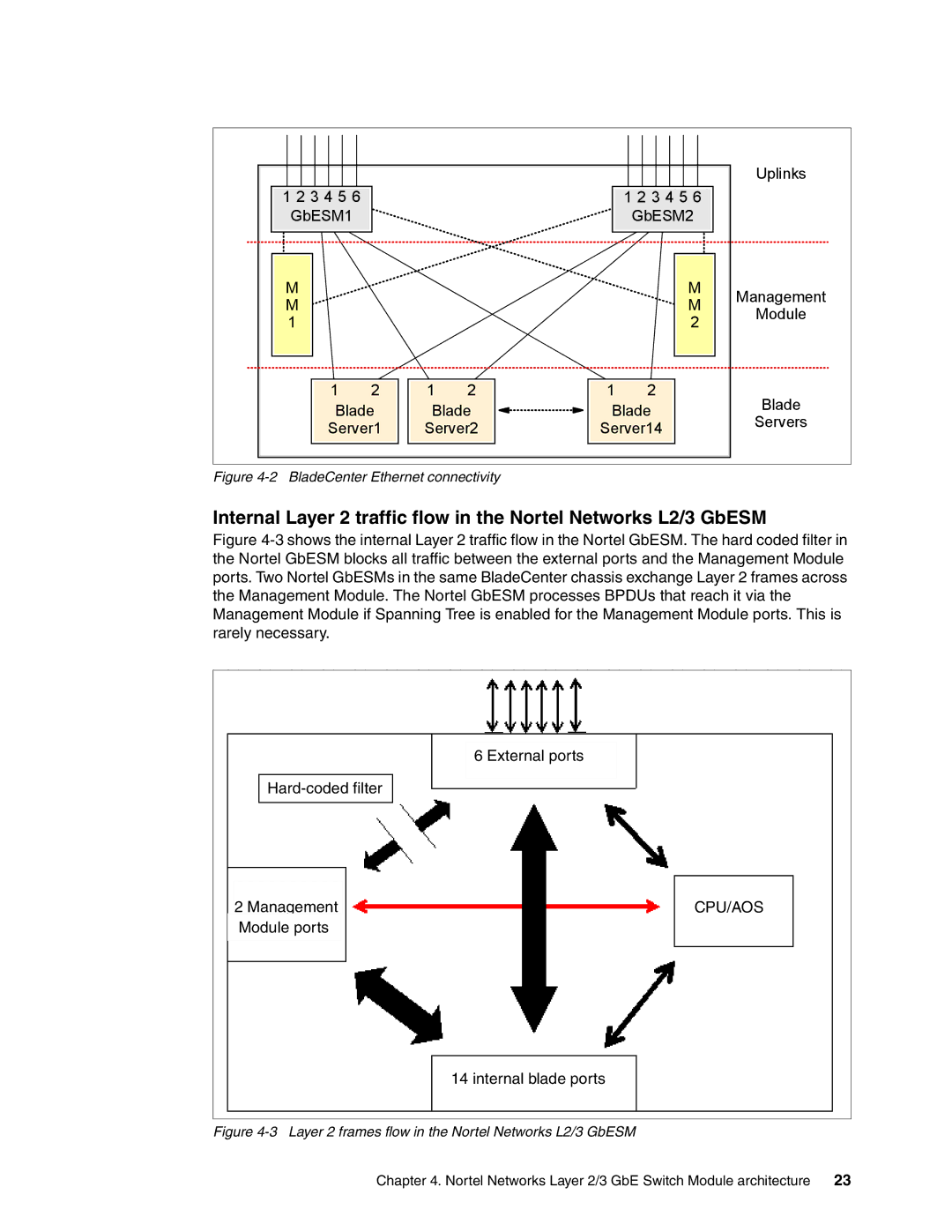
Figure 4-2 BladeCenter Ethernet connectivity
Internal Layer 2 traffic flow in the Nortel Networks L2/3 GbESM
Figure 4-3 shows the internal Layer 2 traffic flow in the Nortel GbESM. The hard coded filter in the Nortel GbESM blocks all traffic between the external ports and the Management Module ports. Two Nortel GbESMs in the same BladeCenter chassis exchange Layer 2 frames across the Management Module. The Nortel GbESM processes BPDUs that reach it via the Management Module if Spanning Tree is enabled for the Management Module ports. This is rarely necessary.
6 External ports
Hard-coded filter
2Management Module ports
CPU/AOS
14 internal blade ports
Figure 4-3 Layer 2 frames flow in the Nortel Networks L2/3 GbESM
Chapter 4. Nortel Networks Layer 2/3 GbE Switch Module architecture | 23 |