For blade server 1, a team is made using the first Ethernet interface as the primary and the second as standby. The IP address for the new BASP interface is set to 10.20.0.1. This is called Active/Standby mode.
Note: First Ethernet interface refers to the blade’s physical connection to the first Ethernet switch module in slot 1.
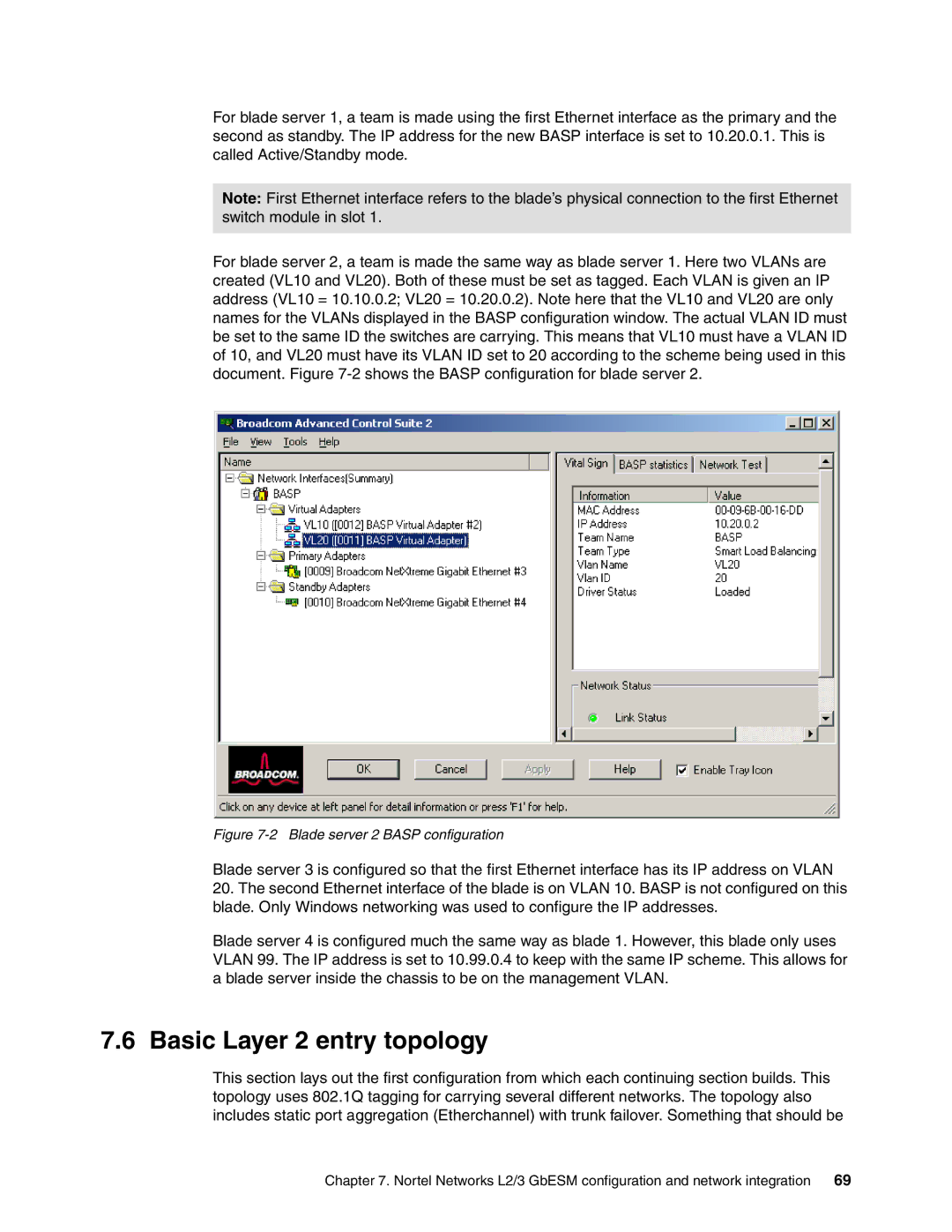
For blade server 2, a team is made the same way as blade server 1. Here two VLANs are created (VL10 and VL20). Both of these must be set as tagged. Each VLAN is given an IP address (VL10 = 10.10.0.2; VL20 = 10.20.0.2). Note here that the VL10 and VL20 are only names for the VLANs displayed in the BASP configuration window. The actual VLAN ID must be set to the same ID the switches are carrying. This means that VL10 must have a VLAN ID of 10, and VL20 must have its VLAN ID set to 20 according to the scheme being used in this document. Figure
Figure 7-2 Blade server 2 BASP configuration
Blade server 3 is configured so that the first Ethernet interface has its IP address on VLAN
20.The second Ethernet interface of the blade is on VLAN 10. BASP is not configured on this blade. Only Windows networking was used to configure the IP addresses.
Blade server 4 is configured much the same way as blade 1. However, this blade only uses VLAN 99. The IP address is set to 10.99.0.4 to keep with the same IP scheme. This allows for a blade server inside the chassis to be on the management VLAN.
7.6 Basic Layer 2 entry topology
This section lays out the first configuration from which each continuing section builds. This topology uses 802.1Q tagging for carrying several different networks. The topology also includes static port aggregation (Etherchannel) with trunk failover. Something that should be
Chapter 7. Nortel Networks L2/3 GbESM configuration and network integration 69