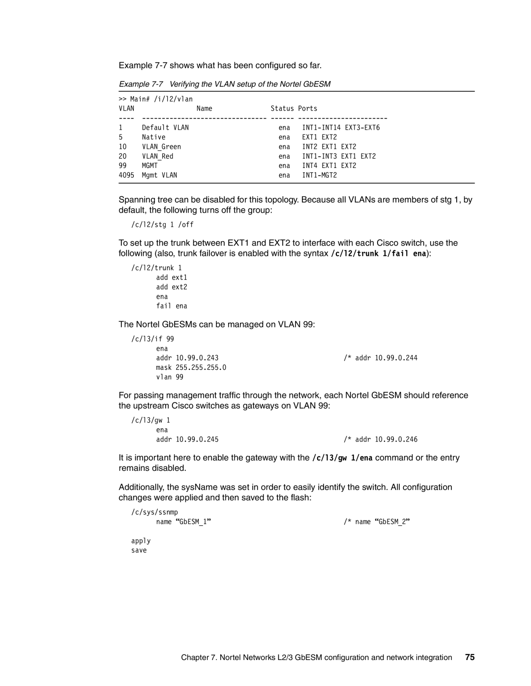
Example 7-7 shows what has been configured so far.
Example 7-7 Verifying the VLAN setup of the Nortel GbESM
>> Main# /i/l2/vlan |
|
|
|
| |
VLAN | Name | Status Ports |
|
| |
1 | Default VLAN | ena | |||
5 | Native | ena | EXT1 | EXT2 |
|
10 | VLAN_Green | ena | INT2 | EXT1 | EXT2 |
20 | VLAN_Red | ena | EXT1 EXT2 | ||
99 | MGMT | ena | INT4 | EXT1 | EXT2 |
4095 | Mgmt VLAN | ena |
| ||
|
|
|
|
|
|
Spanning tree can be disabled for this topology. Because all VLANs are members of stg 1, by default, the following turns off the group:
/c/l2/stg 1 /off
To set up the trunk between EXT1 and EXT2 to interface with each Cisco switch, use the following (also, trunk failover is enabled with the syntax /c/l2/trunk 1/fail ena):
/c/l2/trunk 1 add ext1 add ext2 ena fail ena
The Nortel GbESMs can be managed on VLAN 99:
/c/l3/if 99 |
|
ena |
|
addr 10.99.0.243 | /* addr 10.99.0.244 |
mask 255.255.255.0 |
|
vlan 99 |
|
For passing management traffic through the network, each Nortel GbESM should reference the upstream Cisco switches as gateways on VLAN 99:
/c/l3/gw 1 |
|
ena |
|
addr 10.99.0.245 | /* addr 10.99.0.246 |
It is important here to enable the gateway with the /c/l3/gw 1/ena command or the entry remains disabled.
Additionally, the sysName was set in order to easily identify the switch. All configuration changes were applied and then saved to the flash:
/c/sys/ssnmp |
|
name “GbESM_1” | /* name “GbESM_2” |
apply |
|
save |
|
Chapter 7. Nortel Networks L2/3 GbESM configuration and network integration 75
