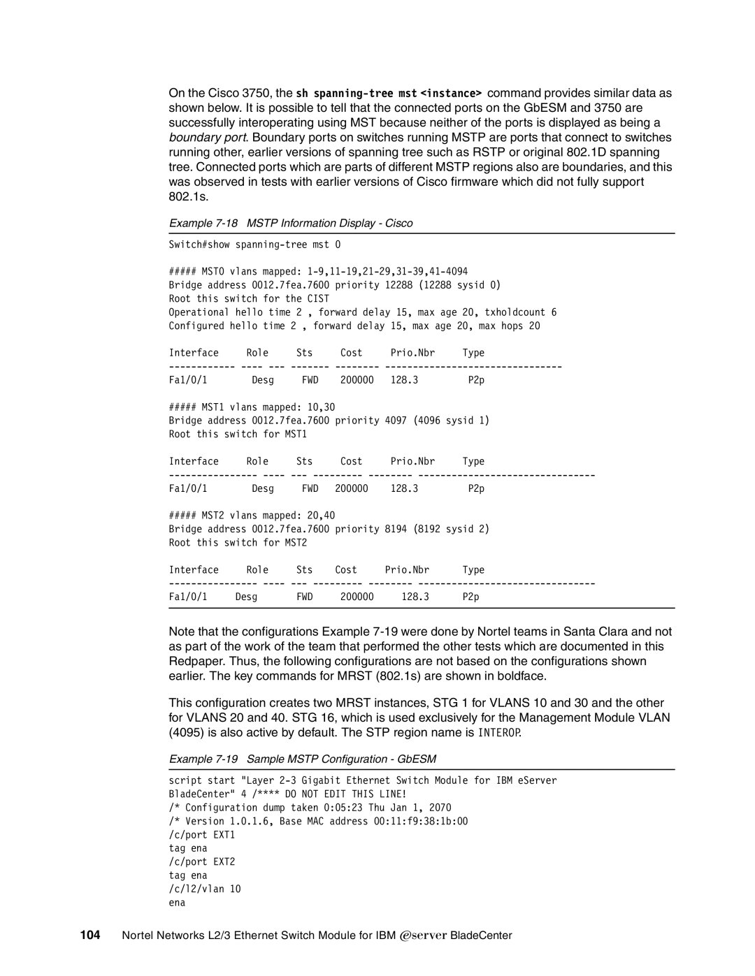
On the Cisco 3750, the sh
Example 7-18 MSTP Information Display - Cisco
Switch#show
#####MST0 vlans mapped:
Bridge address 0012.7fea.7600 priority 12288 (12288 sysid 0) Root this switch for the CIST
Operational hello time 2 , forward delay 15, max age 20, txholdcount 6 Configured hello time 2 , forward delay 15, max age 20, max hops 20
Interface | Role | Sts | Cost | Prio.Nbr | Type | |
Fa1/0/1 | Desg | FWD | 200000 | 128.3 | P2p | |
##### MST1 vlans | mapped: 10,30 |
|
|
| ||
Bridge address 0012.7fea.7600 priority 4097 (4096 sysid 1) | ||||||
Root this switch | for MST1 |
|
|
| ||
Interface | Role | Sts | Cost | Prio.Nbr | Type | |
Fa1/0/1 | Desg | FWD | 200000 | 128.3 | P2p | |
##### MST2 vlans | mapped: 20,40 |
|
|
| ||
Bridge address 0012.7fea.7600 priority 8194 (8192 sysid 2) | ||||||
Root this switch | for MST2 |
|
|
| ||
Interface | Role | Sts | Cost | Prio.Nbr | Type | |
Fa1/0/1 | Desg |
| FWD | 200000 | 128.3 | P2p |
|
|
|
|
|
|
|
Note that the configurations Example
This configuration creates two MRST instances, STG 1 for VLANS 10 and 30 and the other for VLANS 20 and 40. STG 16, which is used exclusively for the Management Module VLAN (4095) is also active by default. The STP region name is INTEROP.
Example 7-19 Sample MSTP Configuration - GbESM
script start "Layer
/* Configuration dump taken 0:05:23 Thu Jan 1, 2070 /* Version 1.0.1.6, Base MAC address 00:11:f9:38:1b:00 /c/port EXT1
tag ena /c/port EXT2 tag ena /c/l2/vlan 10 ena
104Nortel Networks L2/3 Ethernet Switch Module for IBM Eserver BladeCenter