Electrical
7.4Reserved or Unused Signals
The following are the general types of reserved (RSVD) signals and connection guidelines:
•RSVD – these signals should not be connected
•RSVD_TP – these signals should be routed to a test point
•RSVD_NCTF – these signals are
Arbitrary connection of these signals to VCC, VDDQ, VSS, or to any other signal (including each other) may result in component malfunction or incompatibility with future processors. See Signal Description on page 82 for a pin listing of the processor and the location of all reserved signals.
For reliable operation, always connect unused inputs or
7.5Signal Groups
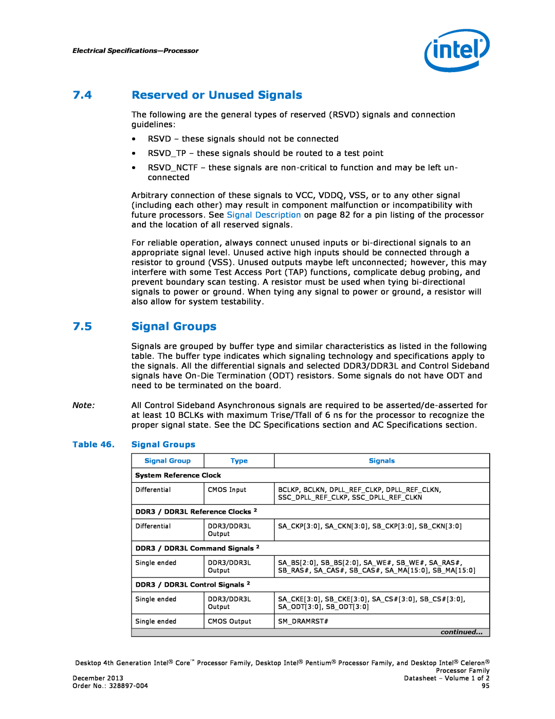
Signals are grouped by buffer type and similar characteristics as listed in the following table. The buffer type indicates which signaling technology and specifications apply to the signals. All the differential signals and selected DDR3/DDR3L and Control Sideband signals have
Note: All Control Sideband Asynchronous signals are required to be
Table 46. | Signal Groups |
|
|
|
|
|
|
| Signal Group | Type | Signals |
|
|
|
|
| System Reference Clock |
| |
|
|
|
|
| Differential | CMOS Input | BCLKP, BCLKN, DPLL_REF_CLKP, DPLL_REF_CLKN, |
|
|
| SSC_DPLL_REF_CLKP, SSC_DPLL_REF_CLKN |
|
|
|
|
| DDR3 / DDR3L Reference Clocks 2 |
| |
| Differential | DDR3/DDR3L | SA_CKP[3:0], SA_CKN[3:0], SB_CKP[3:0], SB_CKN[3:0] |
|
| Output |
|
|
|
|
|
| DDR3 / DDR3L Command Signals 2 |
| |
| Single ended | DDR3/DDR3L | SA_BS[2:0], SB_BS[2:0], SA_WE#, SB_WE#, SA_RAS#, |
|
| Output | SB_RAS#, SA_CAS#, SB_CAS#, SA_MA[15:0], SB_MA[15:0] |
|
|
|
|
| DDR3 / DDR3L Control Signals 2 |
| |
| Single ended | DDR3/DDR3L | SA_CKE[3:0], SB_CKE[3:0], SA_CS#[3:0], SB_CS#[3:0], |
|
| Output | SA_ODT[3:0], SB_ODT[3:0] |
|
|
|
|
| Single ended | CMOS Output | SM_DRAMRST# |
continued...
Desktop 4th Generation Intel® Core™ Processor Family, Desktop Intel® Pentium® Processor Family, and Desktop Intel® Celeron® Processor Family
December 2013 | Datasheet – Volume 1 of 2 |
Order No.: | 95 |