Hardware Design
3.8UTOPIA Level 2 Interface
The IXP43X network processors support the
The UTOPIA module is configured as a master and can support
The IXP43X network processors are in compliance with the ATM Forum, UTOPIA Level 2 Specification, Revision 1.0. For optimal design results, the guidelines of the specification should be followed.
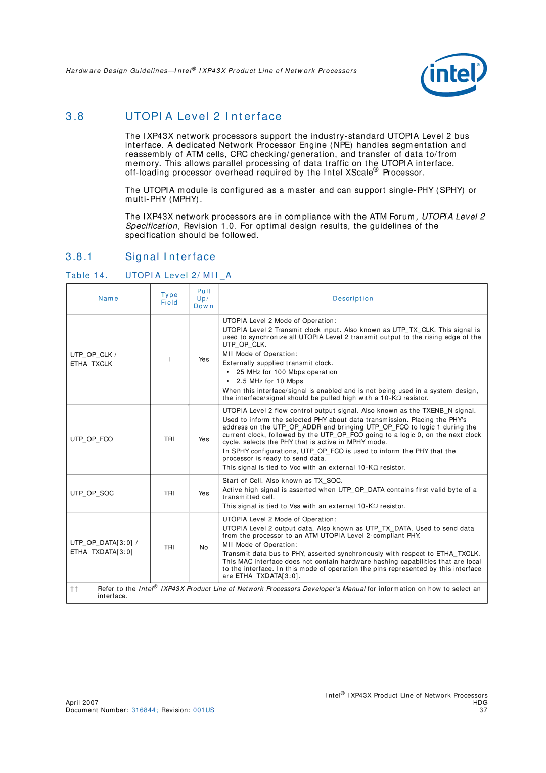
3.8.1Signal Interface
Table 14. | UTOPIA Level 2/MII_A | |||||
|
|
|
|
|
| |
|
|
| Type | Pull |
| |
| Name |
| Up/ | Description | ||
|
| Field | ||||
|
|
| Down |
| ||
|
|
|
|
| ||
|
|
|
|
|
| |
|
|
|
|
| UTOPIA Level 2 Mode of Operation: | |
|
|
|
|
| UTOPIA Level 2 Transmit clock input. Also known as UTP_TX_CLK. This signal is | |
|
|
|
|
| used to synchronize all UTOPIA Level 2 transmit output to the rising edge of the | |
|
|
|
|
| UTP_OP_CLK. | |
UTP_OP_CLK / |
| I | Yes | MII Mode of Operation: | ||
ETHA_TXCLK |
| Externally supplied transmit clock. | ||||
|
|
| ||||
|
|
|
|
| • 25 MHz for 100 Mbps operation | |
|
|
|
|
| • 2.5 MHz for 10 Mbps | |
|
|
|
|
| When this interface/signal is enabled and is not being used in a system design, | |
|
|
|
|
| the interface/signal should be pulled high with a | |
|
|
|
|
|
| |
|
|
|
|
| UTOPIA Level 2 flow control output signal. Also known as the TXENB_N signal. | |
|
|
|
|
| Used to inform the selected PHY about data transmission. Placing the PHY’s | |
|
|
|
|
| address on the UTP_OP_ADDR and bringing UTP_OP_FCO to logic 1 during the | |
UTP_OP_FCO |
| TRI | Yes | current clock, followed by the UTP_OP_FCO going to a logic 0, on the next clock | ||
| cycle, selects the PHY that is active in MPHY mode. | |||||
|
|
|
|
| ||
|
|
|
|
| In SPHY configurations, UTP_OP_FCO is used to inform the PHY that the | |
|
|
|
|
| processor is ready to send data. | |
|
|
|
|
| This signal is tied to Vcc with an external | |
|
|
|
|
|
| |
|
|
|
|
| Start of Cell. Also known as TX_SOC. | |
UTP_OP_SOC |
| TRI | Yes | Active high signal is asserted when UTP_OP_DATA contains first valid byte of a | ||
| transmitted cell. | |||||
|
|
|
|
| ||
|
|
|
|
| This signal is tied to Vss with an external | |
|
|
|
|
|
| |
|
|
|
|
| UTOPIA Level 2 Mode of Operation: | |
|
|
|
|
| UTOPIA Level 2 output data. Also known as UTP_TX_DATA. Used to send data | |
UTP_OP_DATA[3:0] / |
|
| from the processor to an ATM UTOPIA Level | |||
TRI | No | MII Mode of Operation: | ||||
ETHA_TXDATA[3:0] | Transmit data bus to PHY, asserted synchronously with respect to ETHA_TXCLK. | |||||
|
| |||||
|
|
|
|
| This MAC interface does not contain hardware hashing capabilities that are local | |
|
|
|
|
| to the interface. In this mode of operation the pins represented by this interface | |
|
|
|
|
| are ETHA_TXDATA[3:0]. | |
|
|
|
|
| ||
†† | Refer to the Intel® IXP43X Product Line of Network Processors Developer’s Manual for information on how to select an | |||||
| interface. |
|
|
| ||
|
|
|
|
|
| |
| Intel® IXP43X Product Line of Network Processors |
April 2007 | HDG |
Document Number: 316844; Revision: 001US | 37 |