Intel® IXP43X Product Line of Network
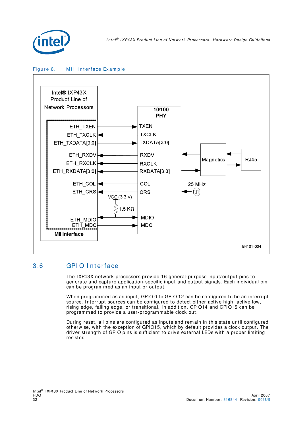
Figure 6. MII Interface Example
Intel® IXP43X |
|
|
| |
Product Line of |
|
|
| |
Network Processors | 10/100 |
|
| |
|
|
| ||
| PHY |
|
| |
ETH_TXEN | TXEN |
|
| |
ETH_TXCLK | TXCLK |
|
| |
ETH_TXDATA[3:0] | TXDATA[3:0] |
|
| |
ETH_RXDV | RXDV | Magnetics | RJ45 | |
ETH_RXCLK | RXCLK | |||
|
| |||
ETH_RXDATA[3:0] | RXDATA[3:0] |
|
| |
ETH_COL | COL | 25 MHz |
| |
ETH_CRS | CRS |
|
| |
| VCC (3.3 V) |
|
| |
| 1.5 KΩ |
|
| |
ETH_MDIO | MDIO |
|
| |
ETH_MDC | MDC |
|
| |
MII Interface |
|
|
| |
|
|
| B4101 |
3.6GPIO Interface
The IXP43X network processors provide 16
When programmed as an input, GPIO 0 to GPIO 12 can be configured to be an interrupt source. Interrupt sources can be configured to detect either active high, active low, rising edge, falling edge, or transitional. In addition, GPIO14 and GPIO15 can be programmed to provide a
During reset, all pins are configured as inputs and remain in this state until configured otherwise, with the exception of GPIO15, which by default provides a clock output. The driver strength of GPIO pins is sufficient to drive external LEDs with a proper limiting resistor.
Intel® IXP43X Product Line of Network Processors |
|
HDG | April 2007 |
32 | Document Number: 316844; Revision: 001US |