SECTION 13—ELECTRONICS
![]()
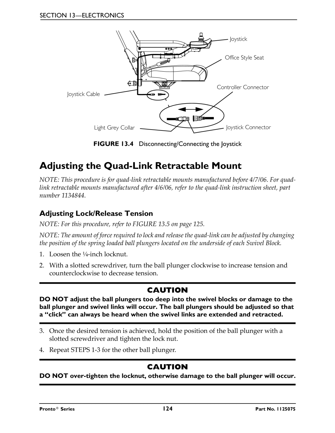
![]() Joystick
Joystick
Office Style Seat
Controller Connector
Joystick Cable
Light Grey Collar | Joystick Connector |
FIGURE 13.4 Disconnecting/Connecting the Joystick
Adjusting the Quad-Link Retractable Mount
NOTE: This procedure is for
Adjusting Lock/Release Tension
NOTE: For this procedure, refer to FIGURE 13.5 on page 125.
NOTE: The amount of force required to lock and release the
1.Loosen the
2.With a slotted screwdriver, turn the ball plunger clockwise to increase tension and counterclockwise to decrease tension.
CAUTION
DO NOT adjust the ball plungers too deep into the swivel blocks or damage to the ball plunger and swivel links will occur. The ball plungers should be adjusted so that a “click” can always be heard when the swivel links are extended and retracted.
3.Once the desired tension is achieved, hold the position of the ball plunger with a slotted screwdriver and tighten the lock nut.
4.Repeat STEPS
CAUTION
DO NOT
Pronto® Series | 124 | Part No. 1125075 |