HELIX DN9340E/DN9344E Remote Control Software
User Guide
At the Filter Mode tab
Use the Unit Display drop down menu to set the display mode that DN9340 units should assume when taken out of slave operation; this only comes into effect if the slave is a DN9430. The choice made here has no effect on your AddIn device display.
To Bypass all the Filters on the current channel
Tick the Bypass check box in the Filter Mode tab by clicking on it.
To add a Filter to the graph
1Click on the
Add
button in the Filter Shaping tab. A notch filter, with target, appears on the
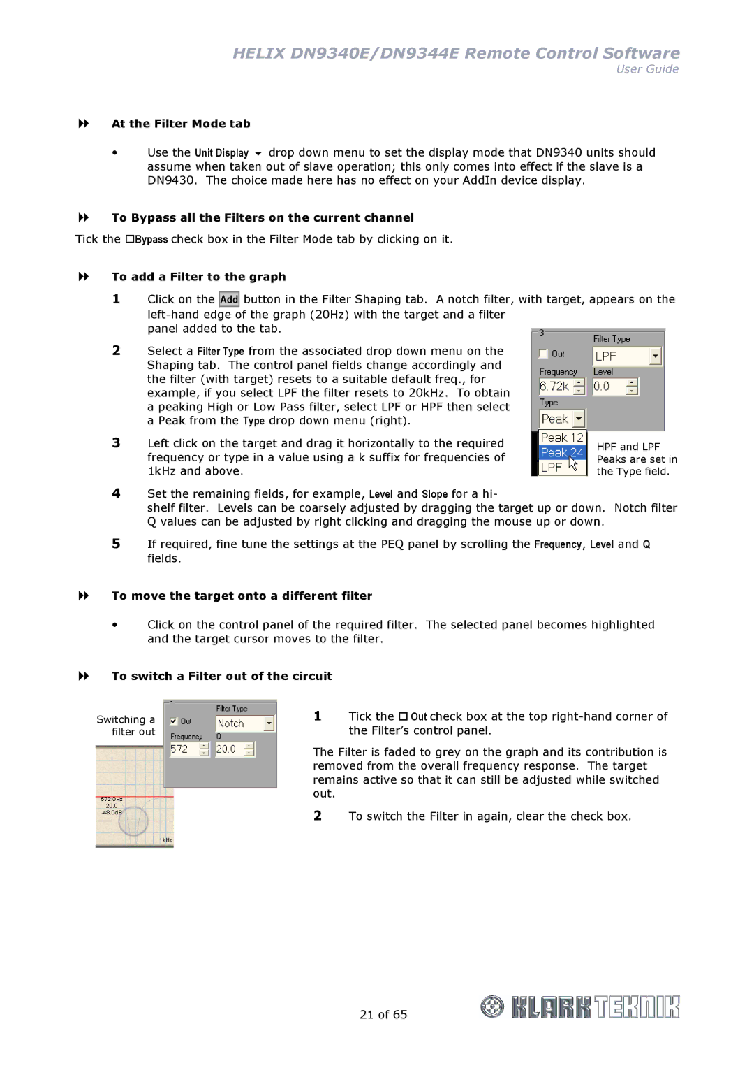
2Select a Filter Type from the associated drop down menu on the Shaping tab. The control panel fields change accordingly and the filter (with target) resets to a suitable default freq., for example, if you select LPF the filter resets to 20kHz. To obtain a peaking High or Low Pass filter, select LPF or HPF then select a Peak from the Type drop down menu (right).
3Left click on the target and drag it horizontally to the required frequency or type in a value using a k suffix for frequencies of 1kHz and above.
HPF and LPF Peaks are set in the Type field.
4Set the remaining fields, for example, Level and Slope for a hi-
shelf filter. Levels can be coarsely adjusted by dragging the target up or down. Notch filter Q values can be adjusted by right clicking and dragging the mouse up or down.
5If required, fine tune the settings at the PEQ panel by scrolling the Frequency, Level and Q fields.
To move the target onto a different filter
Click on the control panel of the required filter. The selected panel becomes highlighted and the target cursor moves to the filter.
To switch a Filter out of the circuit
Switching a filter out
1Tick the Out check box at the top
The Filter is faded to grey on the graph and its contribution is removed from the overall frequency response. The target remains active so that it can still be adjusted while switched out.
2To switch the Filter in again, clear the check box.
21 of 65