HELIX DN9340E/DN9344E Remote Control Software
User Guide
4CONFIGURING THE HELIX ADDIN
4.1Network Identification
A single show file will usually have multiple HELIX AddIns equating to the networked HELIX units in your physical set up. Each AddIn must be uniquely addressed and configured to match its physical counterpart, that is, the slave DN9340 or DN9344 HELIX that it will remotely program, and also the communication mode must be specified. In addition, to make it easier to navigate between device screens without confusion, device screens and channels should be labelled. All this is done in the Home view of the HELIX AddIn.
To configure the HELIX AddIn to match its physical counterpart
1Switch to the Home view from the Channel A or B Navigation Strip, or by clicking on the upper or lower Home tab.
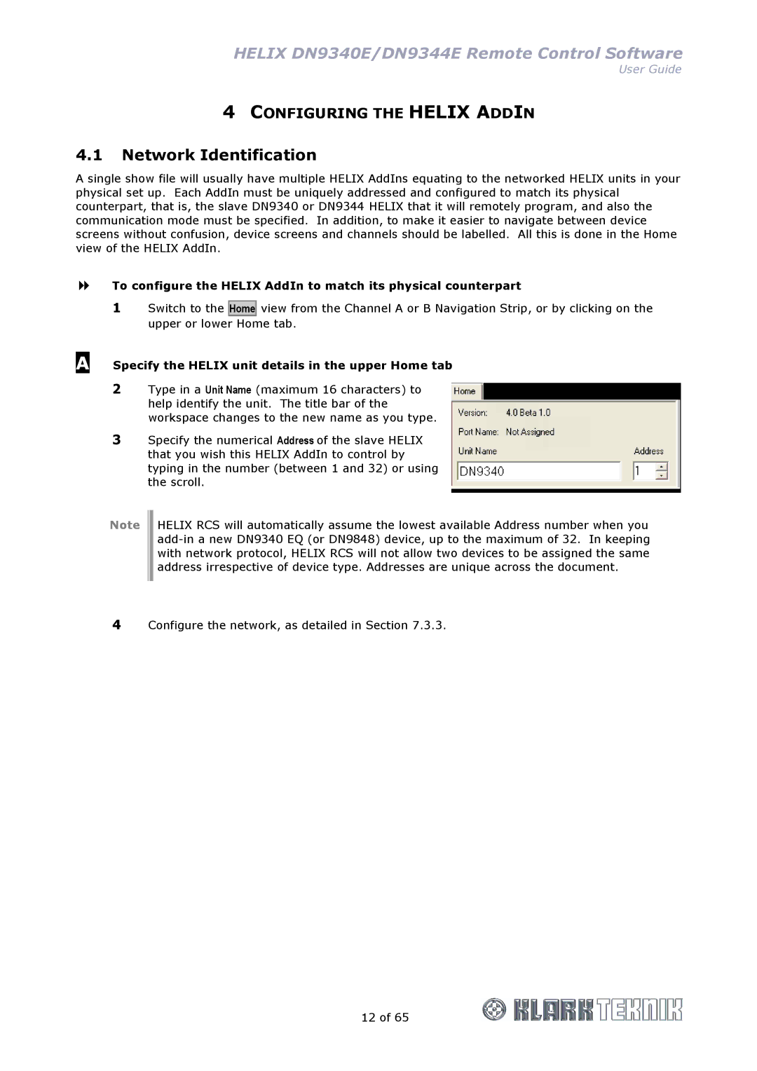
A Specify the HELIX unit details in the upper Home tab
2Type in a Unit Name (maximum 16 characters) to help identify the unit. The title bar of the workspace changes to the new name as you type.
3Specify the numerical Address of the slave HELIX that you wish this HELIX AddIn to control by typing in the number (between 1 and 32) or using the scroll.
Note
HELIX RCS will automatically assume the lowest available Address number when you
4Configure the network, as detailed in Section 7.3.3.
12 of 65