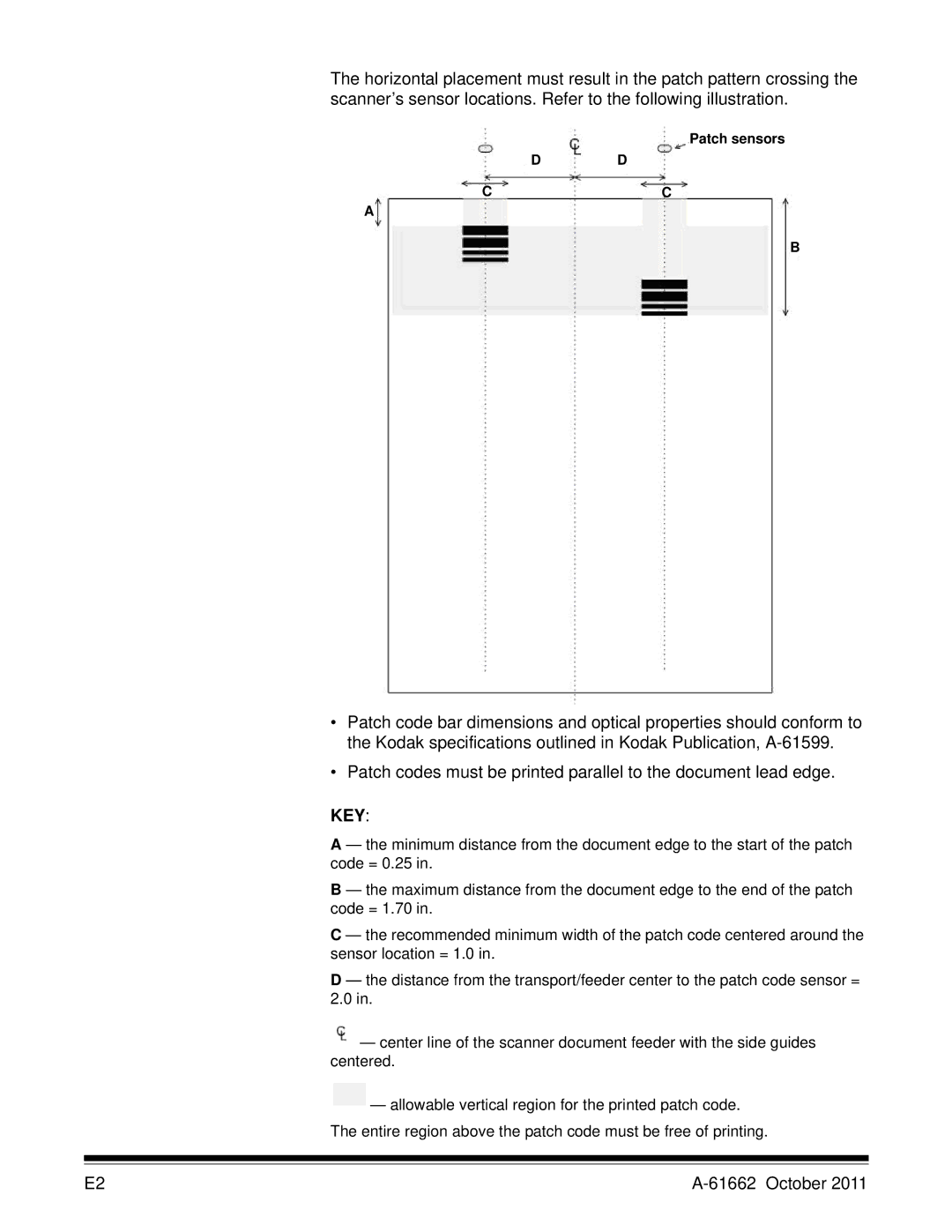
The horizontal placement must result in the patch pattern crossing the scanner’s sensor locations. Refer to the following illustration.
Patch sensors
D D
CC
A
B
•Patch code bar dimensions and optical properties should conform to the Kodak specifications outlined in Kodak Publication,
•Patch codes must be printed parallel to the document lead edge.
KEY:
A — the minimum distance from the document edge to the start of the patch code = 0.25 in.
B — the maximum distance from the document edge to the end of the patch code = 1.70 in.
C — the recommended minimum width of the patch code centered around the sensor location = 1.0 in.
D — the distance from the transport/feeder center to the patch code sensor = 2.0 in.
![]() — center line of the scanner document feeder with the side guides centered.
— center line of the scanner document feeder with the side guides centered.
![]() — allowable vertical region for the printed patch code. The entire region above the patch code must be free of printing.
— allowable vertical region for the printed patch code. The entire region above the patch code must be free of printing.
E2 |