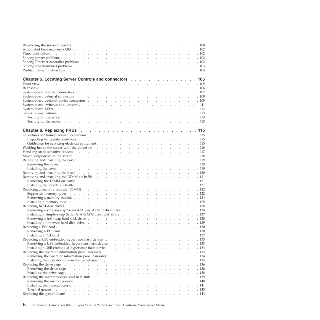
RS210 specifications
The Lenovo RS210 is an innovative and compact server designed to meet the demands of small to medium-sized businesses and edge computing environments. As part of Lenovo's robust server line, the RS210 delivers enhanced performance, efficiency, and reliability, making it a perfect fit for businesses looking to optimize their IT infrastructure.One of the standout features of the RS210 is its compact design, which allows it to fit seamlessly into space-constrained environments. With a 1U rack-mountable form factor, the RS210 is ideal for organizations that need to maximize their data center space without sacrificing performance. This small footprint is complemented by Lenovo's intelligent cooling technology, which helps maintain optimal operating temperatures while reducing energy consumption.
The RS210 is powered by the latest Intel Xeon processors, delivering exceptional processing power and providing a scalable solution for growing business needs. With support for both single and dual-processor configurations, it can handle a wide range of workloads, allowing businesses to run applications efficiently. The server also features up to 128GB of DDR4 RAM, ensuring that it can manage multiple simultaneous tasks seamlessly.
Storage capabilities are another strong point for the RS210, as it supports a variety of storage options, including SAS, SATA, and SSD drives. This flexibility enables organizations to configure the server to meet their specific storage requirements while ensuring high-performance access to data. Additionally, the RS210 supports RAID configurations, providing redundancy and data protection, which is crucial for maintaining business continuity.
Networking in the RS210 is fortified by multiple Gigabit Ethernet ports, ensuring robust connectivity options. This feature is vital for organizations that require reliable communication between servers and network devices. For enhanced security, Lenovo has incorporated built-in features such as Trusted Platform Module (TPM) for hardware-based security and secure access options to safeguard sensitive data.
Lenovo's commitment to management and monitoring is evident in the RS210, as it includes the Lenovo XClarity Controller. This integrated management tool simplifies server administration, allowing IT teams to deploy, monitor, and manage the server efficiently, leading to reduced operational costs and increased uptime.
In conclusion, the Lenovo RS210 stands out in the market as a compact, powerful, and versatile server solution designed for a variety of workloads. With its impressive processing power, flexible storage options, and robust management features, it is well-equipped to support the evolving needs of modern businesses, making it a reliable choice for IT professionals looking to invest in a future-proof server infrastructure.
